


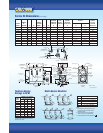
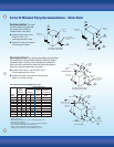
Burner Mounting Plates and Adapter Plates
FRONT VIEW
SIDE VIEWS
4” STANDARD
IDENTIFICATION NUMBER
‘A’
DIA
HOLE
‘B’ DIA
BOLT CIRCLE
‘C’
(REF)
4 8
8” EXTENDED
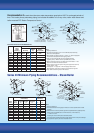
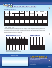
CAST IRON BURNER MOUNTING PLATES
STANDARD BURNER
ADAPTER PLATE
I.D. ‘A’ ‘B’ ‘C’
BOILER MODEL PART NO. NO. DIA. DIA. REF.
24-03 THRU 24-05 330400 920 4-3/4 10 7-1/16
24-06 THRU 24-08 330401 921 6-1/8 10 7-1/16
24-09 THRU 24-12 330402 922 6-3/4 10 7-1/16
BECKETT (“CF” SERIES) BURNER ADAPTER PLATE
I.D. ‘A’ ‘B’ ‘C’
BOILER MODEL PART NO. NO. DIA. DIA. REF.
24-03 THRU 24-06 330400 920 4-3/4 10 7-1/16
24-07 THRU 24-08 330401 921 6-1/8 10 7-1/16
24-09 THRU 24-11 330403 923 7-1/4 10 7-1/16
24-12 330404 924 8-1/8 10 7-1/16
BECKETT (“CG” SERIES) BURNER ADAPTER PLATE
Note:
1. A burner adapter plate is needed for each boiler.
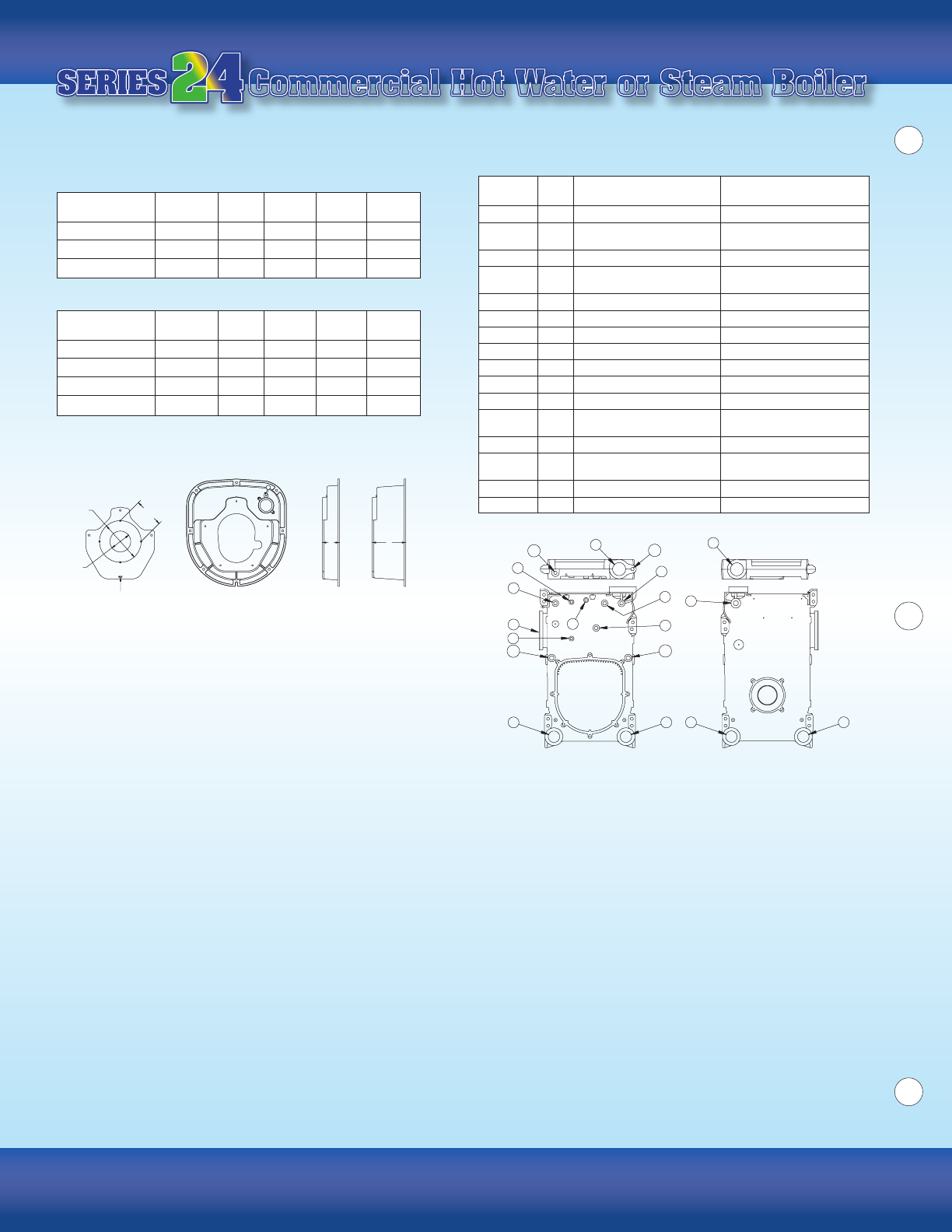
Control Tappings
TAPPING SIZE
LOCATION (IN.) STEAM BOILER W
ATER BOILER
A 4 Supply Supply
B 4
Plug (24-03 thru 24-06)
Plug
Supply (24-07 thru 24-12)
C 3 Blow-Off Valve Return
D 3 Return
Plug (24-03 thru 24-11)
Return (24-12)
E 3 Plug Blow-Off / Drain Valve
F 3 Plug Plug
G 1-1/2 Safety Valve / Surface Skim Tap Relief Valve
J1 1 Plug Plug
J2 1 Float L.W.C.O. Plug
K 3/4 Plug Probe L.W.C.O.
M 3/4 Operating Pressure Limit Control Operating Temperature Limit Control
N 3/4
Hi Pressure Hi Temperature
Limit Control / Manual Reset Limit Control/Manual Reset
P 1/2 Gauge Glass/#67 L.W.C.O. Plug
Q 1/2
Steam Gauge (Bush to 1/4”)
Temperature/Pressure
Gauge (Bush to 1/4”)
S 3/4 Tankless Heater Control Tankless Heater Control
T 3/4 Firing Rate Pressure Control Firing Rate Temperature Control
Series 24 Minimum Piping
Recommendations – Water Boiler
Impact of System Piping – Many hot water systems
are zoned. Some also use mixing valves to control the water
temperature in the system.
These features can cause the
flow through the boiler to vary dramatically, depending on
the status of the zones or mixing valves. In addition, the
large water content of many commercial systems has the
potential to subject the boiler to operation with low return
temperatures for an extended period of time.
These factors
can shorten the life of a boiler due to thermal shock or flue
gas condensation.
Crown’s 3 Recommendations – On the following
pages, CROWN provides three basic recommendations
for near-boiler piping that are intended to maximize the
life expectancy of the boiler by protecting it from flue gas
condensation and thermal shock. Each protects the boiler
by making sure that both of the following conditions are met:
■ The flow through the boiler is high enough to
ensure a temperature rise of less than 40°F
■ The return temperature does not fall below 135°F
for an extended period of time.
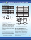
RTC Return Temperature Control – Piping
Recommendation 3 makes use of CROWN’s optional
R
TC (Return Temperature Control). This control provides an
economical and effective way of protecting the boiler from
thermal shock and condensation. It can be incorporated into
most hot water systems with minimal modifications to the
system design and operation. When this option is used on
multiple Series 24s, one R
TC is required for each boiler.
The CROWN RTC is also available with an outdoor reset
option. This provides additional energy savings by
modulating system water temperature to match the
building load requirements.
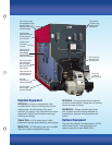
Commercial Hot Water or Steam BoilerCommercial Hot Water or Steam Boiler
FRONT VIEW BACK VIEW
F E
J2
J2
J1
J1
Q
K
M
G
T
B
P
P
N
S
A
D
C