


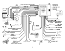

WIRING
GRAY WIRE: PIN 6: Engine Monitor (used for tach mode only)
Used to monitor when the engine is running. Connect to negative terminal of ignition coil, crankshaft position
sensor or ECM/PCM tach wire. An alternate method is to wrap several turns around a spark plug wire and fasten
with wire ties or hi-temp plastic clamps. See programming selection for engine monitor type on page 10 under
“Remote Start Programming Options”.
GREEN WIRE: PIN 7: DOOR TRIGGER (for negative [grounding] switch)
Identify the wire that reads ground when any door is open and 12 volts when all doors are closed. Connect this to
the green door trigger wire to allow the alarm to trigger when any door is open. Some vehicles use a diode to
isolate driver door. In this case you need to run an additional wire from the other doors to this trigger wire to allow
triggering from any door.
BLUE WIRE: PIN 8: HOOD/TRUNK TRIGGER (Grounding switch type / Mandatory Connection!)
This wire is an input trigger for a grounding hood or trunk pin switch. It is used to trigger the alarm and also to
inhibit remote start if the hood is open. Connect to existing hood and trunk pin switches, which read ground when
open. Diode isolate existing switches to avoid any feedback to, or from vehicle's electrical system. If no existing
switches are available, install new pin switches (it may be necessary to drill a hole) and connect to BLUE wire of
alarm. Note: DO NOT mount new pin switches in water pathways.
PURPLE WIRE: PIN 9: DOOR TRIGGER (positive type switch)
Same as green wire above except this wire is used for vehicles that show a positive voltage (12 volts) when the
door is open such as Ford.
YELLOW WIRE: PIN 10: BRAKE INPUT (for positive switch)
Connect this wire to the foot brake switch wire that goes to 12 volts when the foot brake is depressed. This input
is used to reset remote start after entering the running vehicle and turning the ignition key on.
4