


WIRING
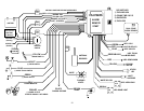
J-1 6 PIN HI-CURRENT CONNECTORS (See Wire diagram at back of manual for Details)
RED: +12V INPUT
RED: +12V INPUT (30 Amp)
BROWN: IGNITION 1 (Secondary Ign. Output)
YELLOW: IGNITION 1 (Primary Ign. Output AND Input)
ORANGE: ACCESSORY (20 Amp)
PURPLE: STARTER OUTPUT
J-2 10 PIN MAIN HARNESS PLUG
WHITE WIRE: PIN 1: PARKING LIGHT CIRCUIT
Connect to switched parking light wire at back of light switch. If this is not possible, connect directly to one of the
parking lights at the front of the vehicle. This wire has an in-line fuse to prevent excessive current from being
drawn from the system. European may vehicles require separate right and left circuits. Use a dual relay or 2
diodes to separate the output signal.
RED WIRE: PIN 2: Alarm Power (10 amp fuse)
Connect to +12 Volt source. Recommended location for this connection is at the vehicle battery positive
terminal.
BROWN WIRE: PIN 3: + SIREN OUTPUT (2 amp max. output)
Connect to RED siren wire.
BLACK WIRE: PIN 4: SYSTEM CHASSIS GROUND
Connect to chassis metal of the vehicle. Scrape away any paint or dirt from the connection point to ensure a
good connection. We recommend the kick panel area for your ground point.
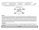
ORANGE WIRE: PIN 5: STARTER KILL / NEGATIVE ARMED OUTPUT
Provides continuous 150mA ground output when system is armed. This output is used for disabling the starter
when the system is armed and/or to activate other devices such as scanner LED’s, window modules, voice
modules etc. For starter kill, cut starter wire and connect between 87A and 30 on relay. Connect orange wire to
85 and connect 86 to Ignition voltage that has power in crank position.
3