


Installation
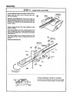
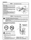
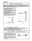
STEP 7 Install Lights and Lenses
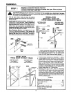
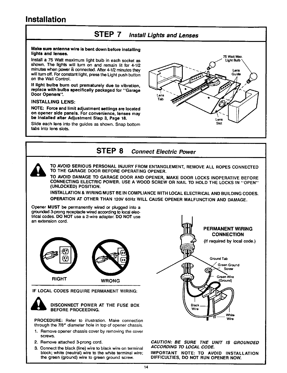
Make sure antenna wire is bent down before installing
lights and lenses.
Install a 75 Watt maximum light bulb in each socket as
shown. The lights will turn on and remain lit for 4-1/2
minutes when power i-sconnected. After 4-1/2 minutes they
will turn off. Forconstant light, press the Light push button
on the Wall Control.
If light bulbs burn out prematurely due to vibration,
replace with bulbs specifically packaged for "Garage
Door Openers".
INSTALLING LENS:
NOTE: Force and limit adjustment settings are located
on opener side panels. For convenience, lenses may
be installed after Adjustment Step 3, Page 18.
Slide each lens into the guides as shown. Snap bottom
tabs into lens slots.
Lens
Tab
75 WattMax.
LightLensBUlb_
Guide
f//
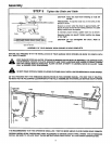
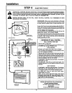
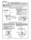
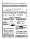
STEP 8 Connect Electric Power
TO AVOID SERIOUS PERSONAL INJURY FROM ENTANGLEMENT, REMOVE ALL ROPES CONNECTED
TO THE GARAGE DOOR BEFORE OPERATING OPENER.
TO AVOID DAMAGE TO GARAGE DOOR AND OPENER, MAKE DOOR LOCKS INOPERATIVE BEFORE
CONNECTING ELECTRIC POWER. USE A WOOD SCREW OR NAIL TO HOLD THE LOCKS IN "OPEN"
(UNLOCKED) POSITION.
INSTALLATION & WIRING MUST BE IN COMPLIANCE WITH LOCAL ELECTRICAL AND BUILDING CODES.
OPERATION AT OTHER THAN 120V 60Hz WILL CAUSE OPENER MALFUNCTION AND DAMAGE.
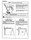
Opener MUST be permanently wired or plugged into a
grounded 3-prong receptacle wired according to local elec-
trical codes. DO NOT use a 2.wire adapter. DO NOT use
an extension cord.
RIGHT WRONG
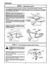
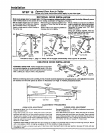
PERMANENT WIRING
CONNECTION
(If required by local code.)
GroundTab
S_v
Green Wire
IF LOCAL CODES REQUIRE PERMANENT WIRING:
DISCONNECT POWER AT THE FUSE BOX
BEFORE PROCEEDING.
PROCEDURE: Refer to illustration. Make connection
through the 7/8" diameter hole in top of opener chassis.
1. Remove opener chassis cover by removing the cover
screws.
2. Remove attached 3-prong cord.
3. Connect the black (line) wire to black wire on terminal
block; white (neutral) wire to the white terminal wire;
the green (ground) wire to green ground screw.
White
Wire
CAUTION: BE SURE THE UNIT IS GROUNDED
ACCORDING TO LOCAL CODE.
IMPORTANT NOTE: TO AVOID INSTALLATION
DIFFICULTIES, DO NOT RUN OPENER NOW.
14