


704530 Rev. A - 2 - Customer First Center · 1121 Highway 74 South · Peachtree City, GA 30269
Port folio
®
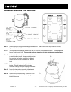
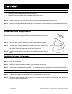
Step 1. Install fixture into ceiling cavity using ½” electrical conduit, ¾” channel, 1½” channel or “ x ½” bar stock as
mounting rails (furnished by others) by inserting them into hanger brackets at both ends of the fixture as shown.
Step 2. Secure mounting rails to support structures.
Step 3. Adjust fixture so bottom of plaster ring is flush with finished ceiling line, using screws securing hanger brackets.
Hanger bracket is reversible for a total adjustment of 5”.
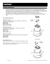
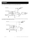
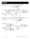
Electrical Connection
CAUTION: Make certain no bare wires are exposed outside of wire nut connectors.
Step 4. Provide electrical service according to the “National Electrical Code” or your local electrical code to the junction
box (located on the plaster frame). Supply wire insulation must be rated for at least 90° C. The junction box is
also rated for a maximum of 12 No. 12 AWG Branch Circuit conductors suitable for at least 90°C.
Step 5. Remove junction box cover.
Step 6. Remove appropriate round pryout and connect conduit to junction box with proper connector (not included).
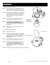
Step 7. Connect supply lead wires to junction box lead wires (line, neutral and ground) in fixture using properly sized
wire nuts (not included). Be careful not to leave any bare conductors outside of the wire nut connectors.
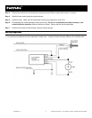
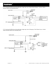
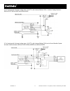
Step 8. 120V or 277V AC Supply: Connect white to white, black to black and green (from electrical service) to the bare
copper wire in the junction box. See the appropriate wiring diagram for more detail.
Place all connections and excess wiring into the junction box and replace cover.