


These instructions do not claim to cover all details or variations in the equipment, procedure, or process described, nor to provide directions for meeting every possible
contingency during installation, operation or maintenance. When additional information is desired to satisfy a problem not covered sufficiently for user’s purpose, please
contact your nearest representative.
Customer First Center • 1121 Hwy 74 South • Peachtree City, GA 30269 IMI-659 ADW051683
Epic/Pole Mounted
Fixtures
Sheet 3 of 4
10/18/05 IMI-659
INSTALLATION INSTRUCTIONS
IMPORTANT: Read carefully before installing fixture. Retain for future reference.
TM
WARNING: Risk of Electric Shock. Disconnect power at fuse or circuit breaker before installing
or servicing.
V
ertically lamped
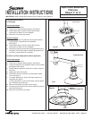
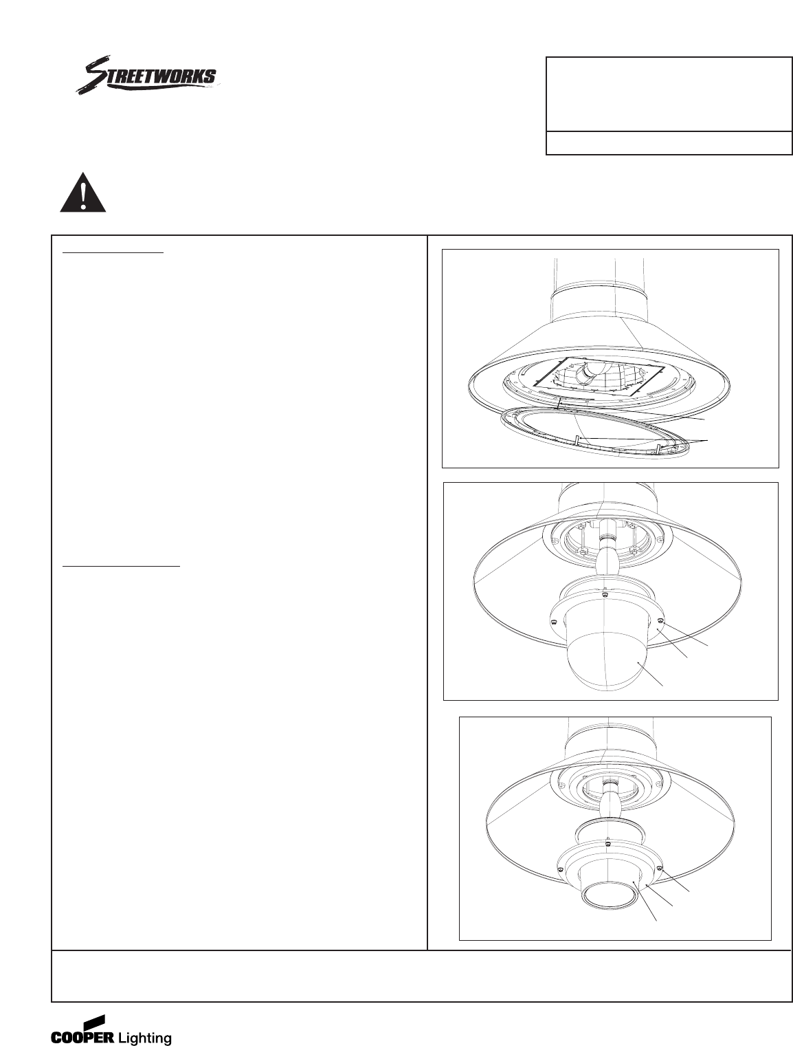
1. Loosen and remove ring retaining screws globe retaining ring
and globe. Components are not tethered.
See Figure 5.
2. Remove two screws on ballast cover followed by ballast
cover. See Figure 7.
3. Unplug optic quick-disconnect.
4. For starter replacement, remove the plug-in starter from
receptacle and replace.
For fuse replacement, unscrew fuse holder cap and replace
fuse. Resecure fuse holder cap.
5. Plug optic quick-disconnect.
6. Resecure the ballast cover with the two screws.
7. Reinstall ring retaining screws securing globe retaining ring
and globe. In the case of type 3 refractive glass globe, use the
mark on globe bottom for orientation.
C. Power Pack Replacement
Horizontally lamped
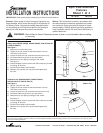
1. Loosen two door screws.
2. Lower door to tethered resting position. See Figure 4.
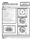
3. Loosen thumbscrew until rectangular washer can be rotated
90 degrees. See Figure 6.
4. Rotate reflector faceplate to release from screws using key
hole slots.
5. Unplug optic quick-disconnect.
6. Remove two screws on ballast cover followed by ballast
cover. See Figure 7.
7. Unplug service quick-disconnect.
8. Holding the handle, loosen the two screws holding the power
pack to the fixture housing. See Figure 8.
9. Holding the handle, rotate the power pack until free and lower.
10. Holding replacement power pack by handle, raise onto screw
heads and rotate.
11. Tighten the two screws while holding power pack in position.
12. Plug together the service quick-disconnect.
13. Resecure the ballast cover with the two screws.
14. Reconnect optic quick-disconnect and secure reflector by
keyhole slots and thumbscrew.
15. Raise door and secure with screws.
Tether
Door Screws
Fig. 4b
Options
Flat Lens or Sag Lens
Ring Retaining Screws
Fig. 5a
Globe Retaining Ring
Globe
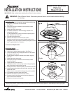
Option MA
Ring Retaining Screws
Fig. 5b
Globe Retaining Ring
Globe
Options
3R & 5R