


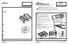

4c. Slipfitter Mount (FIG. 4c)
• The integral slipfitter can be mounted on 2" (2 3/8"
O.D.) pipe. Set screws and a thru bolt are provided to
clamp it securely to the tenon. Thru bolt will require a
drilled hole thru the arm or tenon. Use the slipfitter as a
pattern to drill the thru hole. Secure electrical leads
from the drill path. Remove slipfitter and clean burrs on
tenon from drilled hole. Reinstall the slipfitter. Remove
the cover plate from slipfitter and bring leads into
compartment. Pull power supply leads and the ground
lead into the bottom half of the slipfitter. Be sure the
pivot retainer bolt is tightened securely after aiming is
accomplished. Tighten all mounting bolts per FIG. 4c.
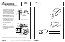
4d. Trunnion Mount (FIG. 4d)
• If the unit is provided with a trunnion which can be
mounted directly on a flat surface (Adapters are
available for installation on building fronts, poles,
crossarms, pipes, etc.) 14-3 SO cable is
recommended for making electrical connection.
The fixture is provided with a grommnet and a strain
relief (approximately 9/16" diameter). To maintain the
seal, screws in the strain relief must be retightened
whenever the seal is disturbed.
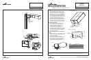
5. Socket Setting Adjustment—Type II or Type III Only
(FIG. 5)
• Socket is normally factory set to provide IES Type II light
distribution pattern. To obtain IES Type III distribution,
proceed as follows (FIG. 5).
• Loosen the two (2) hex head clamping screws
sufficiently for the socket to clear the indexing screws.
• Move socket bracket so that the indexing screws
engage appropriate indexing holes. See table (FIG. 5)
for socket position and resulting light pattern.
These instructions do not claim to cover all details or variations in the equipment, procedure, or process described, nor to provide directions for meeting every possible contingency
during installation, operation or maintenance. When additional information is desired to satisfy a problem not covered sufficiently for user’s purpose, please contact your nearest
representative.
Tribute
Sheet 3 of 4
1/7/08 IMI-685
INSTALLATION INSTRUCTIONS
IMPORTANT : READ CAREFULLY BEFORE INSTALLING FIXTURE.
NOTE: Specifications and dimensions subject to change without notice
Visit our web site at www.cooperlighting.com
Customer First Center 1121 Highway 74 South Peachtree City, GA 30269 770.486.4800 FAX 770.486.4801 ADH070937
FIG. 4c (Slipfitter Mount)
Pivot Retainer Bolt
Torque to 40-50
foot-pounds
3/8-16 x 4”
Hex Head Thru Bolt
with lock nut.
Set screw
Torque to 15-20
foot-pounds
2" [51mm]
3" [77mm]
5 3/8" [137mm]
3 1/2"
[89mm]
FIG. 4d (Trunnion Mount)
Mounting
Holes
3/8-16 Bolt
(Torque to 120-140
inch-pounds)
FIG. 5
Clamping
Screw (2)
Socket
Mount
Indexing
Hole
Indexing
Screw (2)
Light Pattern Socket Index Position
IES Type 250W Clear HPS Lamp All other Clear
(5 3/4” LCL)* HID Lamps (5” LCL)*
II A B
III C D
NOTE: * Light Center Length.