


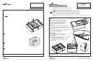
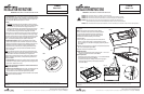
Mounting the fixture
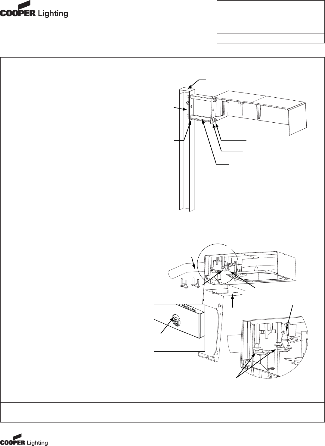
4a. Arm Mount (FIG. 4a)
• Arm Mounting (Square Pole) Lay the fixture on its’ top
with door removed. Remove pole cap allowing nut plate
to be inserted into pole and align with bolt holes. Install
threaded bolts into nut plate. Align arm (end with drain
holes towards pole) and place over threaded bolts.
Align holes in fixture with bolts. Route fixture supply leads
through arm and into pole. Inside of fixture place lock
washer and nuts onto threaded bolts, secure. Housing
and arm must be square with pole. Tighten bolts to 30 ft
lbs. Bolts must not be extended into fixture more than 1".
Finish securing electrical connections inside of pole.
• Arm Mounting (Round Pole) Installation is the same as
square pole except a round pole adapter is used against
the round pole.
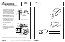
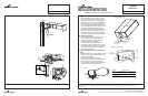
4b. Internal Mast Arm Mount (FIG. 4b)
• Loosen the four tenon clamp bolts for insertion of the
mounting tenon. Note: for the 2" pipe size tenon,
remove the tear away portion of the tenon entrance
gasket. To remove, grasp the aluminum gasket with
pliers and twist off the pre-cut portion of the gasket.
• Pull service lead wires through the mounting tenon until
about 6" extends beyond the tenon end.
• Slide the luminaire onto the tenon while guiding the
service lead wires. Make sure end of tenon is against
stop in housing.
• Tighten 4 tenon clamp bolts. Note: fixture can be
leveled by tightening front bolts differently than rear
bolts. When fixture is level, torque all 4 clamp bolts to
100 inch-pounds. Tighten bolts in alternating pattern.
• Connect service lead wires to fixture leads and anchor
leads in place so they are not in contact with the reflector
surface or ballast surface.
• Replace electrical compartment cover removed in
step 3.
These instructions do not claim to cover all details or variations in the equipment, procedure, or process described, nor to provide directions for meeting every possible contingency
during installation, operation or maintenance. When additional information is desired to satisfy a problem not covered sufficiently for user’s purpose, please contact your nearest
representative.
Tribute
Sheet 2 of 4
1/7/08 IMI-685
INSTALLATION INSTRUCTIONS
IMPORTANT : READ CAREFULLY BEFORE INSTALLING FIXTURE.
NOTE: Specifications and dimensions subject to change without notice
Visit our web site at www.cooperlighting.com
Customer First Center 1121 Highway 74 South Peachtree City, GA 30269 770.486.4800 FAX 770.486.4801 ADH070937
FIG. 4a (Arm Mount)
Cross Sectional View of Fixture Mounted to Pole
Nut Plate
Pole Cap
Arm
Drain Hole
In This
Location
1/2-13 Threaded Rod.
Max. extension into housing
is 1”.
Hex Nut
Lock Washer
FIG. 4b (Internal Mast Arm Mount)
Service Lead Wires
Extend Min. 6”
Tenon Clamp Bolts (qty. 4)
Torque to 100 inch pounds
Electrical
Cover
2” or 1 1/2”
Mounting
Tenon
“A”
Housing
Stop
Detail “A”
Flip Clamps
over for 1 1/2” Pipe
Tear off this part
of gasket for
2” pipe size