


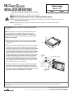

4. With the pole and fixture(s) raised into position, place the power tray
onto the hinges of the housing electrical compartment and let it hang
free. Locate the power connector plug and rotate the power tray until the
connection can be made with the mating connector in the housing. Raise
the power tray until the two (2) thumbscrews engage and tighten until
fully snug. FIG. 3
5. Replace door on the hinges at the rear of the housing, rotate into
position, and assure that both latches are fastened securely.
FIXTURE MAINTENANCE
RELAMPING
1. Disengage both latches and open the door. Do not let the door swing
freely on the hinges.
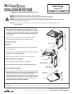
2. Replace the lamp with the appropriate type and wattage and reassemble
the refractor to the upper housing. FIG. 4
3. Close the door and assure that the latches are securely fastened.
NEMA PHOTOCONTROL REPLACEMENT
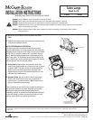
1. The photocontrol is mounted on top the housing. FIG. 5
2. Remove the photocontrol by twisting counterclockwise and replace.
PLUG-IN STARTER REPLACEMENT
1. This procedure applies to fixtures with a plug-in type starter. Disengage
both latches and open the door. Do not let the door swing freely on the
hinges. Loosen the power tray thumbscrews, unplug the power
connector as you lower the powertray, and continue lowering until the
powertray hangs free on the hinges. The starter is located in the position
shown. Remove and replace. Reverse the directions to secure the
powertray and the door after starter replacement.
These instructions do not claim to cover all details or variations in the equipment, procedure, or process described, nor to provide directions for meeting every possible contingency
during installation, operation or maintenance. When additional information is desired to satisfy a problem not covered sufficiently for user’s purpose, please contact your nearest
representative.
Talon Large
Sheet 2 of 3
11/29/07 IMI-682
INSTALLATION INSTRUCTIONS
IMPORTANT: READ CAREFULLY BEFORE INSTALLING FIXTURE.
WARNING: Risk of Fire/Electric Shock. If not qualified, consult an electrician.
WARNING: Risk of Electric Shock. Disconnect power at fuse or circuit breaker before installing or servicing.
WARNING: Risk of Burn. Disconnect power and allow fixture to cool before changing bulb or handling fixture.
WARNING: Risk of Personal Injury. Fixture may become damaged and/or unstable if not installed properly. Tighten all fixture components
to their recommended torque values.
WARNING: Risk of Fire/Electrical Shock. Upside down installation can result in overheating or accumulation of water in fixture.
Install right side up.
NOTE: Specifications and dimensions subject to change without notice.
Visit our web site at www.cooperlighting.com
Customer First Center 1121 Highway 74 South Peachtree City, GA 30269 770.486.4800 FAX 770.486.4801 ADH071365
FIG. 4
Latches
Lamp
Removable Powertray
Lift And Hang On Hinges
Removable Door
Lift And Hang
Door On Hinges
FIG. 3
Power Tray
Thumbscrews (2)
FIG. 5
NEMA Twistlock
Photocontrol