


These instructions do not claim to cover all details or variations in the equipment, procedure, or process described, nor to provide directions for meeting every possible
contingency during installation, operation or maintenance. When additional information is desired to satisfy a problem not covered sufficiently for user’s purpose, please
contact your nearest representative.
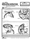
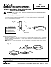
6a.Attach the Pole Clamp (Single Head) -
Attach the POLE CLAMP to the LOWER FLITE ARM using the six (6) 3/8-16 x 0.75” screws provided as depicted in Figure 6a.
Do not tighten the screws completely; leave approximately 1/8” to 1/4” gap between the two parts. This will allow these
parts to slip over the pole with no interference.
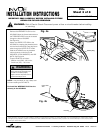
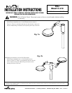
6b.Attach the Pole Clamp (Dual Head) -
Attach the two (2) LOWER FLITE ARM using the six (6) 3/8-16 x 0.75” screws provided as depicted in Figure 6b. Do not tighten
the screws completely; leave approximately 1/8” to 1/4” gap between the two parts. This will allow these parts to slip over the
pole with no interference.
NOTE: Pole Clamps (2) and One set of six (6) 3/8 - 16 x 0.75” screws are not necessary for this assembly. Discard if desired.
Customer First Center • 1121 Hwy 74 South • Peachtree City, GA 30269 IMI-597 AVU040197
Flite
Sheet 5 of 8
8/31/04 IMI-597
INSTALLATION INSTRUCTIONS
IMPORTANT: READ CAREFULLY BEFORE INSTALLING FIXTURE.
RETAIN FOR FUTURE REFERENCE.
TM
WARNING: Risk of Electric Shock. Disconnect power at fuse or circuit breaker before installing
or servicing.
Pole Clamp
Fig. 6a
Fig. 6b
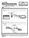
WARNING
Risk of Personal Injury
Fixture may become damaged and/or
unstable if not installed properly
Tighten all fixture components to their
recommended torque values