


10 UVLC Series
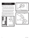
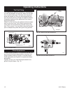
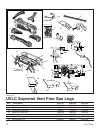
Positioning the Logs
The logs must be positioned on the grate and locating
pins as shown in Figure 8.
Gas logs must be properly positioned or the appliance
will not function properly, and may result in soot accu-
mulation on the inside of the firebox and/or on the gas
logs. Make sure there is no flame impingement on the
logs which could result in excessive carbon monoxide
emissions.
Make sure each bottom log engages the locator pins
on the grate, and top logs are properly positioned in
notches on the tops of the lower logs.
The contents of the small bags of volcanic rock may
only be placed as shown in Figure 8. Apply loose mate-
rial per instructions manual. Do not apply extra material
or material not supplied with the heater. Replace only
with Part No. 57897.
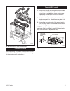
Gas Line Connection
Check the gas type. Use only the gas type indicated on
the appliance rating plate. If the gas listed on the plate
is not the type of gas supplied, DO NOT INSTALL the
log set. Contact your dealer for the proper model.
Always use an external regulator for all LP applances,
to reduce the supply tank pressure to a maximum of
14” w.c. This is in addition to the regulator fitted to the
heater.
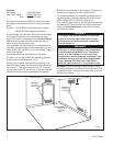
The normal gas connection is made at the left side (fac-
ing the unit). If a right-side connection is desired, the
connecting pipe may be directed under or behind the
rear of the appliance, to terminate at the left-hand side
for connection to the inlet of the appliance.
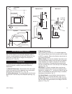
Connect the appliance to the gas line using fittings and
aluminum tubing provided.
Close the valve knob on the appliance, turn the main
gas supply valve ‘ON’ and carefully check all gas con-
nections for leaks, with a soapy water solution or a
sniffer. DO NOT TEST FOR LEAKS WITH AN OPEN
FLAME.
Upon completing your gas line connection, a small
amount of air will be in the gas lines. When first lighting
the pilot, it will take a few minutes for the lines to purge
themselves of air. Once the purging is complete, the
pilot and burner will light and operate as indicated in
this manual. Subsequent lightings of the appliance will
not require purging.
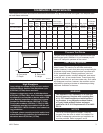
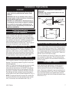
Check the inlet pressure to the appliance, to ensure that
it is as shown in the table on page 2. The minimum is
for the purpose of input adjustment.
The pressure is controlled by the regulator and should
be checked at the pressure test point located in the
control valve body.
The pressure should be checked with the appliance
burning and the control set on ‘HIGH’.
The pressure regulator is preset and locked to avoid
tampering. If the pressure is not as specified, replace
the regulator.
After measuring the pressure, replace the test point
plug. Ensure there are no leaks, then place the logs in
their specified positions.
WARNING
Connection directly to an unregulated LP tank can
cause an explosion.
During the initial purging and subsequent light-
ings, never allow the gas valve control knob to
remain depressed in the ‘Pilot’ position without
lighting the pilot with a match or piezo ignitor.
There is a possibility of odor fade in LP. Never
install an LP appliance or service line below grade
without a gas detector.
WARNING
Failure to position the parts in accordance with
these diagrams or failure to use only parts spe-
cifically approved for use with this appliance may
result in property damage or personal injury.
This appliance is equipped for (natural or pro-
pane) gas. Field conversion is not permitted.