


10 20008055
T111
Bottom view
10/27/03 djt
C
B
Switch
Bottom View
T111
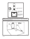
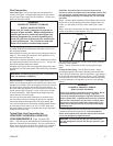
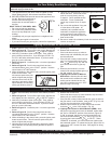
Fig. 7 Route thermostat wire under logset.
T110
remote install
10/27/03 djt
A
B
C
D
E
F
G
H
B
T110
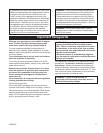
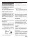
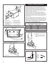
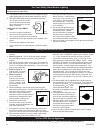
Fig. 6 Wireless remote receiver installation.
A Piezo Ignitor E Battery Terminal
B Mounting Screws F Receiver Bracket
C Lead Wires to Valve G Remote Receiver
(red & white)
D Push-on Retainers H Switch (OFF/ON)
T112
Thermopile switch
10/27/03 djt
B
A
Existing Wiring
T112
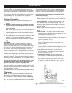
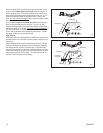
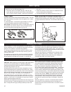
Fig. 8 Thermopile Switch (OFF/ON).
To install your millivolt wall switch, an approved wall box
should be installed in a location suitable to you. The
thermostat wire should be routed from the wall box to
the log set and should be routed underneath the log set
as shown in Figure 7 and pulled up to the valve’s wiring
terminal as shown in Figure 8.
The two wires, letter “A”, should not be removed or
changed. Remove switch wires, Letter B. The two fe-
male ends of your wire can be connected to the two outer
connections just below the screw terminals as shown in
Figures 9 & 10.
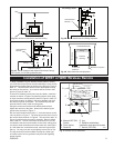
Now the wall switch can be wired as shown in Figure 11.
The red and white wires can be connected to either poles
as they carry only millivolt current. No ground is used at
the wall switch. See the lighting instructions for the mil-
livolt wall switch in the operating manual.
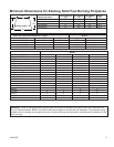
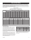
Recommended Maximum Lead Length (Double Wire)
When Using Wall Switch or Thermostat
Wire Size Max. Length
14 ga. 50 ft.
16 ga. 32 ft.
18 ga. 20 ft.
20 ga. 15 ft.
22 ga. 10 ft.
NOTE: Must be stranded wire.
Installation of Millivolt Wall Switch
T113
Thermopile switch
10/27/03 djt
C
B
A
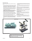
A Thermopile (Do Not Remove)
B Switch
C Wires from Receiver (red &
white) or Wires from Millivolt
Wall
T114
Fig. 9 Connect two (2) female ends to outer connections.
Fig. 10 Fig. 11