


6
PYROMASTER® UVHB10 Vent-Free Heaters
20004232
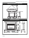
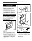
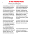
Fig. 8 Typical gas supply installation.
FP297A
1/2" Gas Supply
1/2" NPT x 1/2" Flare Shut-Off
Valve
3/8" Flex Line
(From Valve)
10. Mount the fan on-off control (Rheostat) to the base
with the studs provided and secure with two (2) nuts.
11. Feed the plug through the 4” x 5” hole on the left
side of the heater and plug into a wall receptacle.
12. Reassemble unit by following Steps 1- 3 in reverse
order.
Fan Operation
The FK24 fan has a heat sensor that will not allow the
fan to come on until heater reaches a preset tempera-
ture, approximately 100-120° F. Once the heater
reaches temperature use the speed control knob to turn
fan on and off to adjust fan speed.
Installing Brass Trim
1. Remove brass trim (3 pieces) from carton. Remove
the protective coating from each piece.
2. Using the (2) screws provided, attach the side
pieces to the heater. (Fig. 7)
3. Mount the top trim to the heater. Be sure to overlap
top trim to the front side of the side trim pieces.
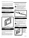
Fig. 7 Install brass trim.
FP1115
Brass Trim (Top)
Brass Trim
(Sides)
Final Assembly
Final assembly is accomplished by lifting the mantel
cabinet overtop of the heater behind the brass trim
pieces.
NOTE: The mantel is designed to fit flush to the wall as
a freestanding unit. If desired, it may be secured to the
wall with nails or screws (not provided).
When installed, the heater must be electri-
cally connected and grounded in accor-
dance with local codes or, in the absence of
local codes:
U.S. INSTALLATIONS: FOLLOW LOCAL CODES
AND THE NATIONAL ELECTRICAL CODE, ANSI/
NFPA NO. 70.
Run Gas Line from Its
Source to the Heater
If gas piping from the source to the heater location has
not been accomplished, install the required pipe.
Consult local plumbing code to assure proper pipe size.
The gas pipeline can be brought in through the right
side of the heater.
NOTE: The gas line connection can be made with
properly tinned 3/8" copper tubing, 1/2" rigid pipe or an
approved flex connector, then reduced to 3/8" to the
heater. Because some municipalities have some
additional local codes, it is always best to consult your
local authority. Consult the current National Fuel Gas
Code, ANSI Z223.1
Always check for gas leaks using a 50/50
soap and water solution. Apply water/soap
solution with a brush -
do not over apply.
NEVER!
test with an open flame.
The gas control is equipped with a captured
screw type pressure test point, therefore it is not
necessary to provide a 1/8" test point up stream of the
control.
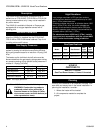
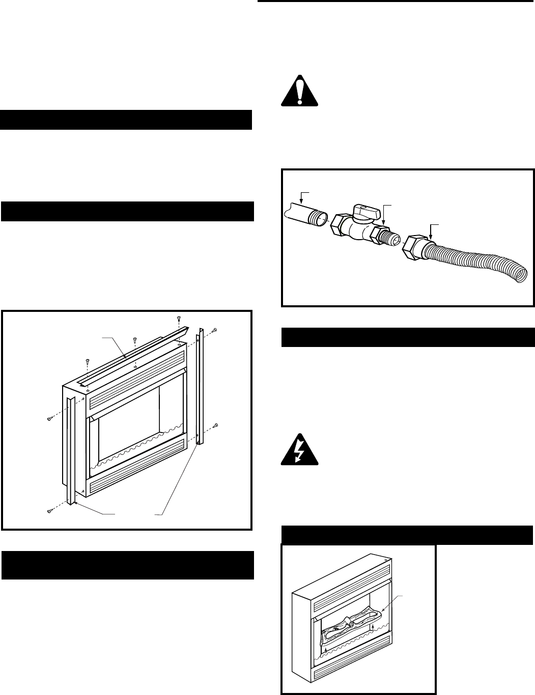
UVHB10 Logset
The UVHB10 is
shipped with the
one piece log in
position. However,
if the log needs to
be removed, let
the log cool, it
may be hot, lift it
straight up . (Fig. 9)
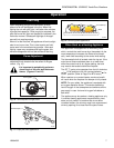
Logset
FP1213
Fig. 9 Remove logset by lifting up. Be
sure logset is cool before handling.