


AEROFAN I&M-1005
USA
www.continentalfan.com
Canada
www.aeroflo.com
CCoonnttiinneennttaall FFaann MMaannuuffaaccttuurriinngg IInncc..
203 Eggert Rd.
Buffalo, NY 14215
Tel: 716-842-0670 Toll: 800-779-4021 Fax: 716-842-0611
AAeerroofflloo IInncc..
12-205 Matheson Blvd. East
Mississauga, ON L4Z 3E3
Tel: 905-890-6192 Toll: 800-779-4021 Fax: 905-890-6193
CCOONNDDEENNSSEEDD WWAARRRRAANNTTYY
All warranty claims must be processed through point of purchase. All warranty repair work must be authorized by Vendor.
AeroFan Superior Bathroom Fans are warranted against defects in material and workmanship for a period of three years from
date of purchase. Warranty does not include consumable components such as lamps. All other products are warranted for a
period of one year from date of purchase.
WWAARRRRAANNTTYY DDOOEESS NNOOTT AAPPPPLLYY TTOO::
• Shipping damage, either concealed or visible. Claims must be filed with the carrier.
• Damage caused by improper installation, wiring, or incorrect electrical voltage.
• Materials that have been modified, altered, or disassembled.
• Damage caused by corrosion, erosion, abrasion or severe temperature.
• Materials that have had the identification labels removed or altered.
• Materials that have been subjected to abuse, misuse, abnormal usage, or accident.
• Materials that have not been properly maintained.
No other warranties, expressed, implied or written shall apply to this product. Vendor will not be responsible for any
consequential or incidental damages, loss of property, revenues or profit, cost of removal, installation, or reinstallation, personal
damage or loss of life, or for any breach of warranty, regardless of how caused.
For a complete description of our Limited Warranty conditions, visit www.continentalfan.com.
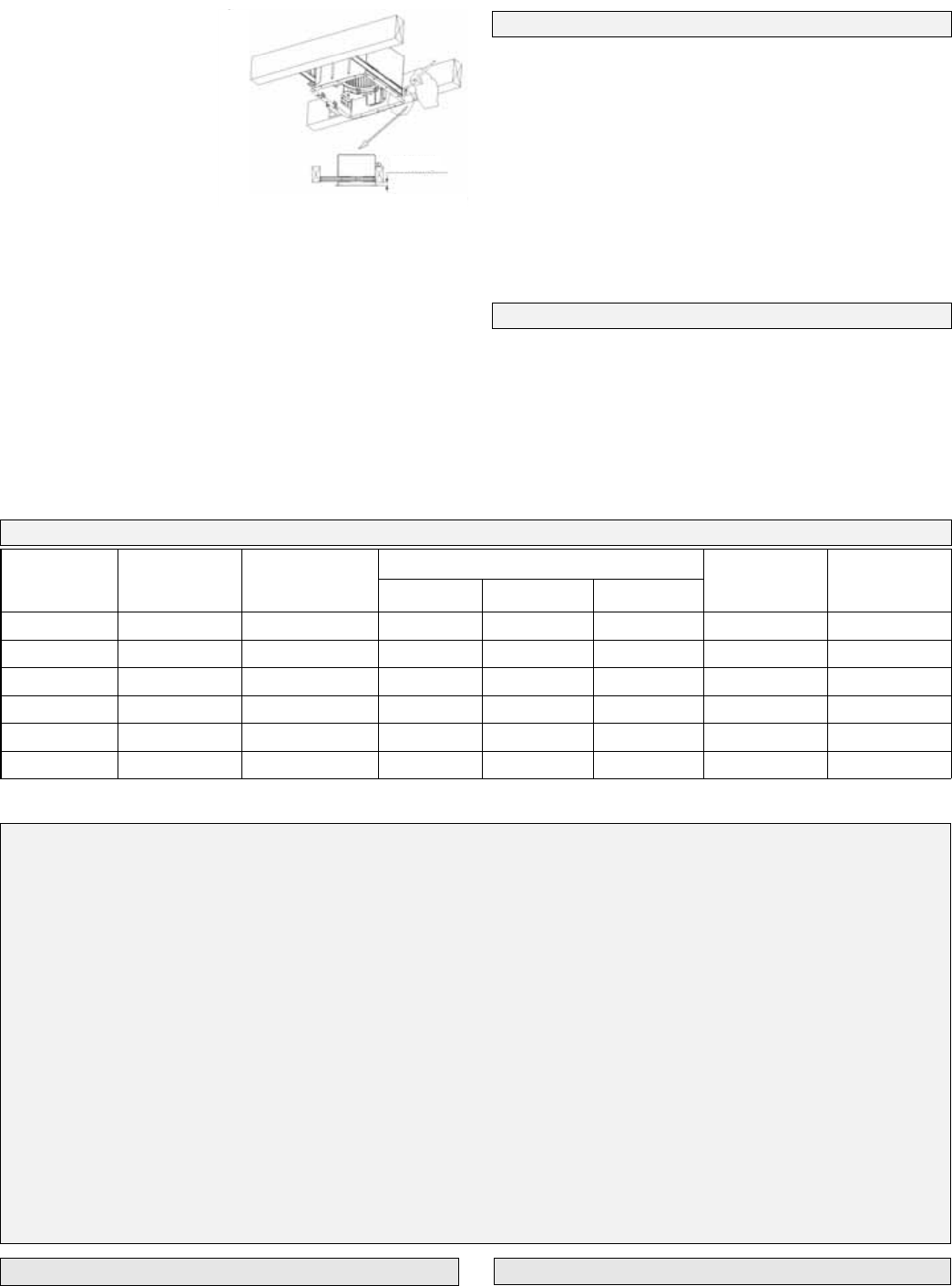
3. To install the housing in
the ceiling, position it
between the joists and
extend the brackets to the
adjacent joists. Mark the
screw locations (at the top
of the keyhole on each
bracket) on the joists.
Note: make sure to allow
the appropriate depth for
the particular ceiling type.
The bottom edge of the
housing should be flush with the ceiling. (Figure 4)
4. Remove the housing and drive the screws part way into the
joists at the marked locations.
5. Mount the housing using the screws in the joists and then
secure them tightly. Make all the electrical connections in
the electrical box, per the wiring diagram, and attach the
electrical box cover. Attach the discharge duct tightly onto
the fan outlet.
Note: In order for the fan to operate efficiently, keep the
discharge duct as straight as possible.
6. To complete the installation, install the lamps (if applicable)
and mount the grille.
MODEL VOLTAGE
(V)
FREQUENCY
(HZ)
POWER CONSUMPTION (W)
SPEED
(RPM)
AIRFLOW
(CFM)
MOTOR PL LAMP NIGHT LIGHT
TBF90 120 60 25 -- -- 750/1050 60/90
TBF120 120 60 40 -- -- 775/1050 90/120
TBFS90L 120 60 25 26 4 750/1050 60/90
TBFS120L 120 60 40 26 4 775/1050 90/120
TBFR90L 120 60 25 26 4 750/1050 60/90
TBFR120L 120 60 40 26 4 775/1050 90/120
FFAANN SSPPEECCIIFFIICCAATTIIOONNSS
RREECCOOMMMMEENNDDEEDD MMAAIINNTTEENNAANNCCEE
1. Turn the power off and lock it out prior to servicing or cleaning.
2. To clean the grille, first remove it from the fan then use a
soft brush and clean water to remove the dirt. If the dirt is
not easily removed, wash with a neutral detergent.
3. In order to remove the impeller and housing for maintenance,
first remove the light, night light and reflector (if applicable).
Then unplug the electrical connection and remove the 4
screws that secure the fan assembly to the housing. To
clean the impeller and housing, remove the motor and then
wash with water or a neutral detergent, as required.
Note: Keep all electrical components away from water. Do not
use corrosive chemicals or water in excess of 60C (140F) to
clean plastic parts.
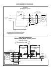
WWIIRRIINNGG PPRROOCCEEDDUURREE
Refer to the wiring diagram.
Ceiling
Figure 4