


13
103509
OWNER’S MANUAL
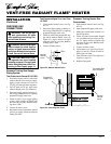
CAUTION: Avoid damage to
control. Hold gas fitting with
wrench when connecting it to gas
piping and/or fittings.
Tee Joint
Reducer
Bushing to
1/8" NPT
1/8" NPT
Plug Tap
Test
Gauge
Connection *
Tee Joint
Pipe
Nipple
Cap
Sediment
Trap
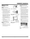
Figure 21 - Gas Connection
* An A.G.A. design-certified manual shutoff valve with 1/8" NPT tap is an acceptable
alternative to test gauge connection. Purchase the optional A.G.A. design-certified manual
shutoff valve from your dealer. See Accessories, page 25.
Pressure
Regulator
3/8" NPT
Pipe Nipple
Ground
Union
Joint
Heater
Cabinet
3" Minimum
Note:
Burner bracket
not shown for clarity
Manual
Shutoff
Valve *
From External
Regulator (11" W.C.
to 14" W.C. Pressure)
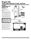
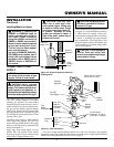
CONNECTING TO GAS
SUPPLY
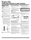
Figure 20 - External Regulator with Vent
Pointing Down
NOTICE: A qualified service per-
son must connect heater to gas
supply. Follow all local codes.
CAUTION: Never connect
heater directly to the propane/LP
supply. This heater requires an ex-
ternal regulator (not supplied). In-
stall the external regulator between
the heater and propane/LP supply.
CAUTION: Use only new,
black iron or steel pipe. Inter-
nally-tinned copper tubing may
be used in certain areas. Check
your local codes. Use pipe of 1/2"
or greater diameter to allow
proper gas volume to heater. If
pipe is too small, undue loss of
pressure will occur.
CAUTION: Use pipe joint seal-
ant that is resistant to liquid pe-
troleum (LP) gas.
The installer must supply an external regu-
lator. The external regulator will reduce
incoming gas pressure. You must reduce
incoming gas pressure to between 11 and 14
inches of water. If you do not reduce incom-
ing gas pressure, heater regulator damage
could occur. Install external regulator with
the vent pointing down as shown in Figure
20. Pointing the vent down protects it from
freezing rain or sleet.
Installation must include a manual shutoff
valve, union, and plugged 1/8" NPT tap.
Locate NPT tap within reach for test gauge
hook up. NPT tap must be upstream from
heater (see Figure 21).
Apply pipe joint sealant lightly to male
threads. This will prevent excess sealant
from going into pipe. Excess sealant in pipe
could result in clogged heater valves.
Install sediment trap in supply line as shown
in Figure 21. Locate sediment trap where it
is within reach for cleaning. Locate sedi-
ment trap where trapped matter is not likely
to freeze. A sediment trap traps moisture
and contaminants. This keeps them from
going into heater controls. If sediment trap
is not installed or is installed wrong, heater
may not run properly.
Propane/LP
Supply Tank
Vent
Pointing
Down
External
Regulator
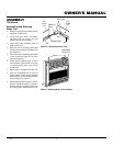
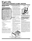
Installing Mantel to Heater
WARNING: If installing the
GHB802 or GHB802A base on
heater, and using with a GA se-
ries heater blower accessory
along with a GS601 surround or a
GM800 or GM900 series mantel,
the surround or mantel clearance
to back wall should be 3/4 inch.
This will improve flame appear-
ance and combustion.
Use only a GHB802B, GHB802C,
OR GHB38 series hearth base if
using a GA series heater blower
accessory with a GM700 series,
GMC32F series, or GMC33U se-
ries mantel.
INSTALLATION
Continued