


4
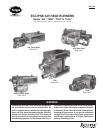
Eclipse AirHeat v1.0 - Installation Guide No. 140, 11/4/03
2.0 Control System Requirements
Turndown Method Input is normally controlled by a motorized butterfly valve in the gas line to the
burner.
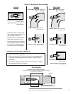
Regulator Loading Lines Connect the top diaphragm chambers of the main gas and pilot gas regulators to the
duct approximately 10" downstream of the burner. This will allow the regulators to
maintain a constant supply pressure to the burner regardless of varying pressures in
the duct.
Piloting Pilot gas flow is adjusted as shown in Figure 6.
Ignition Ignition voltage should be 6000 VAC.
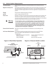
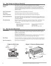
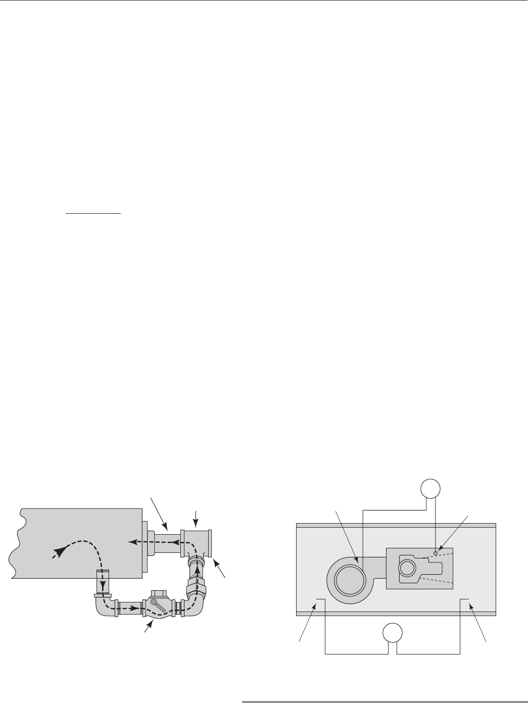
Check Valve
See Figure 3. At high fire, the gas pressure at the burner inlet is higher than the air pressure, and
the check valve is closed. At low fire, gas pressure falls below the air pressure, and the check
valve opens, permitting a small amount of air to mix with the gas. This premix at low fire stabilizes
the flame and helps distribute the flame evenly down the length of the burner.
Do not install any valve or controlling device in the gas line between the
burner and the check valve tee, Figure 3. Because this section of the gas
line carries a partial pemix at low fire, it is possible under unusual condi-
tions for the flame to travel back through the pipe to the tee. Devices in-
stalled in this section may be damaged and may melt, releasing gas to the
atmosphere and causing fires or explosions.
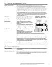
Pressure Switch Connection See Figure 4 for typical connection of combustion air and circulating fan limit
switches.
Limit Controls &Safety Equipment
Limit controls and safety equipment should comply with current NFPA Stan-
dards* 86 and 86C, and all applicable local codes and/or standards.
*Available from:
National Fire Protection Association American National Standard Inst.
Batterymarch Park 1430 Broadway
Quincy, MA 02269 New York, New York 10018
Figure 3–Check Valve Operation Figure 4—Pressure Switch Location
w
Warning
Gas Inlet
Manifold
Check Valve Opens When
Gas Inlet Pressure Is at Low Fire
Process Air
WARNING!
Do Not Install Any Valves Here!
See Section 2.0
Tee
P
HiLo
Blower
Pressure Switch
P
LoHi
Circulating Air
Pressure Switch
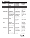
Tube Points
Upstream
Tube Points
Downstream
Tube at
Blower Inlet
Burner Air Ta
p
See Figure 7