


036-21603-002 Rev. A (1004)
6 Unitary Products Group
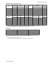
FILTER PERFORMANCE
The airflow capacity data published in the “Blower Perfor-
mance” table listed above represents blower performance
WITHOUT filters. To determine the approximate blower per-
formance of the system, apply the filter drop value for the fil-
ter being used or select an appropriate value from the “Filter
Performance” table shown below.
NOTE: The filter pressure drop values in the “Filter Perfor-
mance” table shown below are typical values for the type of
filter listed and should only be used as a guideline. Actual
pressure drop ratings for each filter type vary between filter
manufacturer.
* Washable fiber are the type supplied with furnace (if supplied).
APPLYING FILTER PRESSURE DROP TO
DETERMINE SYSTEM AIRFLOW
To determine the approximate airflow of the unit with a filter in place,
follow the steps below:
1. Select the filter type.
2. Select the number of return air openings or calculate the return
opening size in square inches to determine the proper filter
pressure drop.
3. Determine the External System Static Pressure (ESP) without
the filter.
4. Select a filter pressure drop from the table based upon the num-
ber of return air openings or return air opening size and add to
the ESP from Step 3 to determine the total system static.
5. If total system static matches a ESP value in the airflow table
(i.e. 0.20 w.c. (50 Pa), 0.60 w.c. (150 Pa), etc,) the system air-
flow corresponds to the intersection of the ESP column and
Model/Blower Speed row.
6. If the total system static falls between ESP values in the table
(i.e. 0.58 w.c. (144 Pa), 0.75 w.c. (187 Pa), etc.), the static pres-
sure may be rounded to the nearest value in the table determin-
ing the airflow using Step 5 or calculate the airflow by using the
following example.
Example: For a 130,000 BTUH (38.06 kW) furnace with 2 return
openings and operating on high-speed blower, it is found that total
system static is 0.58” w.c. To determine the system airflow, complete
the following steps:
Obtain the airflow values at 0.50 w.c. (125 Pa) & 0.60 w.c. (150 Pa)
ESP.
Airflow @ 0.50”: 2125 CFM (60.17 m
3
/min)
Airflow @ 0.60”: 2035 CFM (57.62 m
3
/min)
Subtract the airflow @ 0.50 w.c. (125 Pa) from the airflow @ 0.60
w.c. (150 Pa) to obtain airflow difference.
2035 - 2125 = -90 CFM (2.55 m
3
/min)
Subtract the total system static from 0.50 w.c. (125 Pa) and divide
this difference by the difference in ESP values in the table, 0.60 w.c.
(150 Pa) - 0.50 w.c. (125 Pa), to obtain a percentage.
(0.58 - 0.50) / (0.60 - 0.50) = 0.8
Multiply percentage by airflow difference to obtain airflow reduction.
(0.8) X (-90) = -72
Subtract airflow reduction value to airflow @ 0.50 w.c. (125 Pa) to
obtain actual airflow @ 0.58 inwc (144 Pa) ESP.
2125 - 72 = 2053
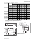
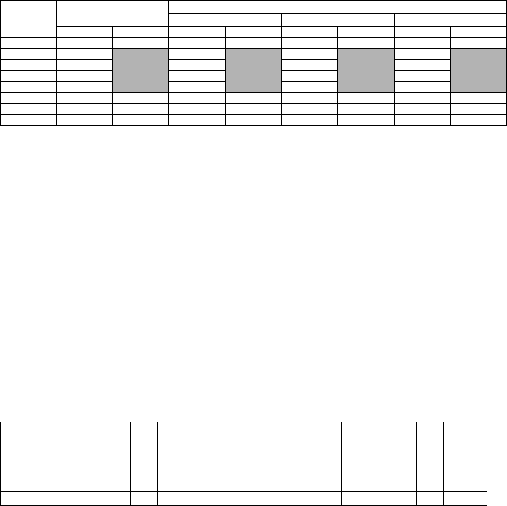
FILTER PERFORMANCE - PRESSURE DROP INCHES W.C.
Airflow
Range
Minimum Opening Size
Filter Type
Disposable WASHABLE FIBER* Pleated
1 Opening 2 Openings 1 Opening 2 Openings 1 Opening 2 Openings 1 Opening 2 Openings
CFM In³ In³ inwc inwc inwc inwc inwc inwc
0 - 750 230
0.01 0.01 0.15
751 - 1000 330 0.05 0.05 0.2
1001 - 1250 330 0.1 0.1 0.2
1251 - 1500 330 0.1 0.1 0.25
1501 - 1750 380 658 0.15 0.09 0.14 0.08 0.3 0.17
1751 - 2000 380 658 0.19 0.11 0.18 0.1 0.3 0.17
2001 & Above 463 658 0.19 0.11 0.18 0.1 0.3 0.17
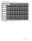
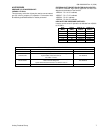
UNIT CLEARANCES TO COMBUSTIBLES (ALL DIMENSIONS IN INCHES)
(ALL SURFACES IDENTIFIED WITH THE UNIT IN AN UPFLOW CONFIGURATION)
APPLICATION
TOP FRONT REAR LEFT SIDE RIGHT SIDE FLUE
FLOOR/
BOTTOM
CLOSET ALCOVE ATTIC
LINE
CONTACT
In. In. In. In. (cm) In. (cm) In. (cm)
UPFLOW 1 6 0 0
3
1
6 COMBUSTIBLE YES YES YES NO
UPFLOW B-VENT 1 3 0 0 0 1 COMBUSTIBLE YES YES YES NO
HORIZONTAL
3
2
6 0 1 0 6 COMBUSTIBLE NO YES YES
YES
3
HORIZONTAL B-VENT 0 3 0 1 0 1 COMBUSTIBLE NO YES YES
YES
3
1 14-1/2” cabinet models only. All other units “0” clearance.
2 14-1/2” cabinet left airflow applications only. All other units and right hand airflow applications “0” clearance.
3 Line contact only permitted between lines formed by the intersection of the rear panel and side panel (top in horizontal position) of the furnace jacket and building joists, studs or
framing.