


English-4
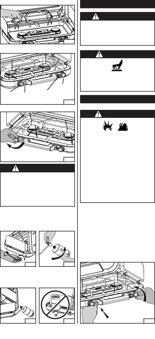
Fig. 13
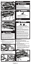
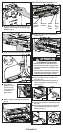
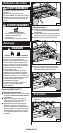
■ Propane cylinder correctly installed.
(Fig. 12)
■ Never operate stove with propane
cylinder in an inverted position. (Fig. 13)
Fig. 10
Fig. 11
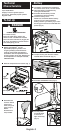
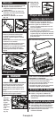
■ Screw regulator into stove hand tight.
(Fig. 10)
■ Remove plastic cap from top of propane
bottle and screw propane bottle into
regulator hand tight. (Fig. 11)
Fig. 12
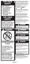
WARNING
• Perform leak test outdoors.
• Extinguish all open flames.
• NEVER leak test when smoking.
• Do not use the outdoor stove until connec-
tion has been leak tested and does not leak.
Leak Check
WARNING
• BURN HAZARD
• Never leave stove unattended when
hot or in use.
• Keep out of reach of children.
To Light
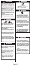
DANGER
• EXPLOSION - FIRE HAZARD
• Propane is heavier than air and can accu-
mulate in low places. If you smell gas, leave
the area immediately.
• Always attach or detach propane source
outdoors; never while stove is lighted, near
flame, pilot lights, other ignition sources or
while stove is hot to touch.
• This stove is red hot during use and can
ignite flammables too close to the burners.
Keep flammables at least 12 inches from
the sides and 48 inches from the top of the
stove. Keep gasoline and other flammable
liquids and vapors well away from stove.
• The stove must not be exposed to flam-
mable vapors or liquids during lighting.
INSTASTART™
Electronic Ignition Stoves
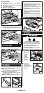
■ Set on sturdy, flat surface. For outdoor
use only.
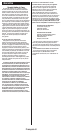
■ Push igniter button and hold; then open
fuel valve fully. (Fig. 14)
■ Repeat for all three burners.
Note: If igniter fails to light stove, replace
the battery with a fresh AA battery. If the
igniter still fails to light stove, use match
to light burner. If the stove is wet the
igniter may not spark.
Fig. 14
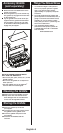
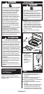
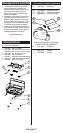
Control Knob Identification (Fig. 8)
CAUTION
• SERVICE SAFETY
• Keep all connections and fittings clean.
Inspect propane cylinder and stove propane
connections for damage before attaching.
• During set up, check all connections and
fittings for leaks using soapy water.
Bubbles indicate a leak. Never use a flame.
■ Close all three burner valves firmly. (Fig. 9)
Fig. 9
Fig. 8
Right
Burner
Valve
Center
Burner
Valve
Igniter
Button
Left
Burner
Valve
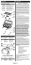
Fig. 7
■ Install pot support as shown. (Fig. 7)