


6
10008388
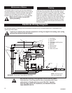
A 15 amp, 120 Volt, 60 Hz circuit with a properly
grounded outlet is required. Preferably, the fireplace
will be on a dedicated circuit as other appliances on
the same circuit may cause the circuit breaker to trip
or the fuse to blow when the heater is in operation.
The unit comes standard with a 6 ft. (1.8 m) long three
wire cord, exiting the right side of the fireplace. Plan
the installation to avoid the use of an extension cord.
Extension cords are for temporary use only. If an extension
cord must be used, it must be UL/CSA certified, rated at 15A
(1875W), 125V maximum with 14 AWG minimum and con-
structed of two current carrying conductors with ground. A
heavy duty extension cord with the shortest length possible
for the connection is recommended and must not be longer
than 50 ft. (15.2 m). Do not coil or cover the extension cord.
Electrical Connection
Electrical outlet wiring must comply with
local building codes and other applicable
regulations to reduce the risk of fire,
electrical shock and injury to persons.
Do not use this fireplace if any part of it
has been under water. Immediately call a
qualified service technician to inspect the
fireplace and replace any part of the elec-
trical system which has been under
water.
WARNING:This procedure must be conducted by a
qualified electrician, in accordance with National and
local codes. In the U.S.A., the installation must con-
form to the National Electrical Code, ANSI/NFPA No.
70. In Canada, the installation must conform to the
current CSA C22.1 Canadian Electrical Code.
WARNING: Make sure the power to the unit is off, and
the power cord is unplugged from the wall outlet
before proceeding with this conversion. Failure to do
so may result in property damage, personal injury or
loss of life.
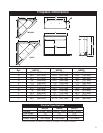
This instruction is intended as a guide for replacing the
power cord supplied with Models HEF22/26/33 electric
fireplace with direct (hard) wiring.
NOTE: When direct wiring this appliance, it must be
connected to a 15 Amp dedicated circuit breaker or
fuse in the electrical panel of the dwelling. The cable
between the circuit/fuse panel and the fireplace must
meet all local and national codes, and in no case shall
the wires be less than 14 gauge.
1. Make sure the power to the unit has been turned
off, the power cord is unplugged from the wall outlet
and the unit has cooled down if it has been operat-
ing.
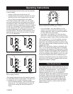
2. Follow Steps 3 through 6 in “Replacing Light Bulbs”
section, Page 7, to gain access to control panel
behind the touchpad controls.
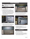
3. Locate where the power cord enters the control
compartment on the right hand side of the unit.
Using wire cutters, cut the power cord within three
inches (75mm) of the point where it exits the cabi-
net.
4. Carefully separate the three (3) wires of the power
cord into separate wires by gently pulling them
apart. DO NOT use a knife, as this may expose
bare conductor. The hot wire is connected on the
right hand side and is terminated with a 90° termi-
nal (marked as “power” on the control board). The
neutral wire is connected on the left hand side and
is terminated with a straight terminal marked as
“Neutral” on the control board. The green ground
wire is attached to a ground stud.
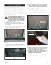
5. Using wire strippers, strip approximately 5/8"
(15mm) from the ends of the hot and neutral wires.
6. Using a wrench, remove the #10-24 hex nut from
the ground stud where the green wire from the
power cord is attached. Remove and discard the
green wire. Reinstall the nut but do not tighten yet.
7. While standing on the right side of the unit, locate
the power cord where it exits the cabinet. Using pli-
ers, gently cut and remove the power cord. Dispose
of the power cord.
Direct (Hard) Wiring Electric Fireplace
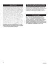
Grounding Instructions
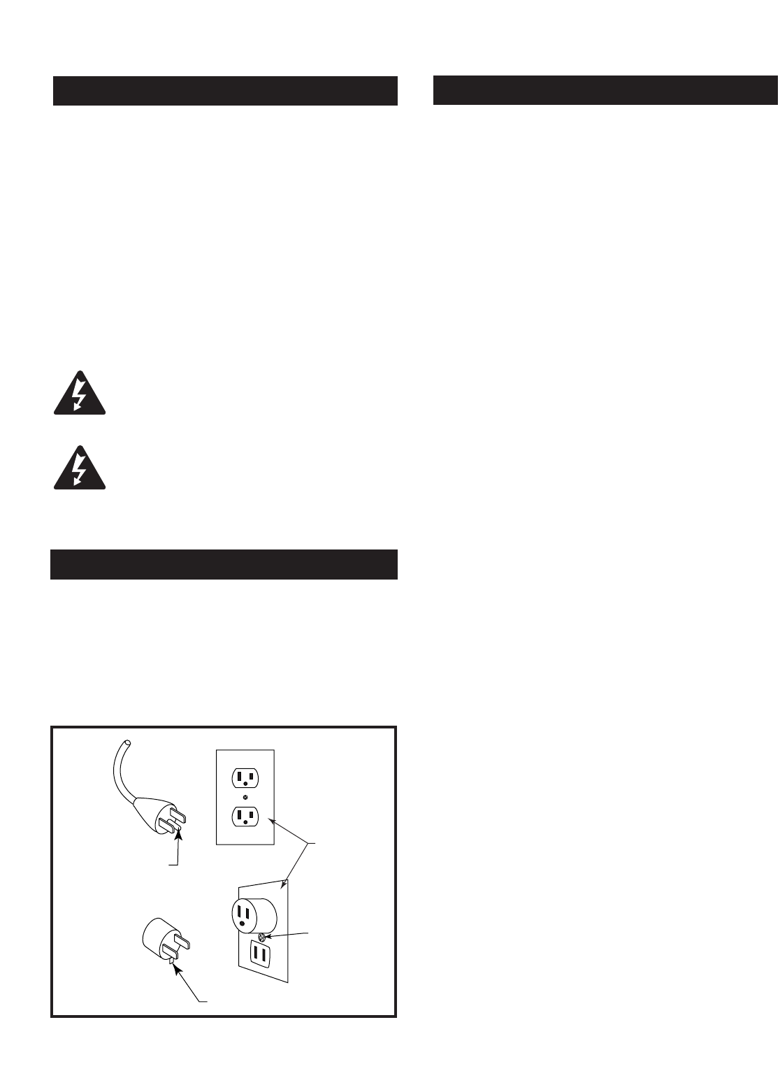
This heater is for use on 120 volts. The cord has a
plug as shown at A in Figure 1. An adapter as shown
at C is available for connecting three-blade grounding-
type plugs to two-slot receptacles. The green ground-
ing lug extending from the adapter must be connected
to a permanent ground such as a properly grounded
outlet box. The adapter should not be used if a three-
slot grounded receptacle is available.
A
B
C
Grounding Means
Cover of
Grounded
Outlet Box
Metal Screw
Grounding Pin
Adapter
Fig. 1 Grounding methods.