


7
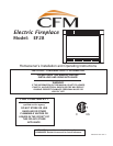
EF28 Electric Fireplace
10010019
• Direct (Hard) Wiring Electric Fireplace
This instruction is intended as a guide for replacing the power cord supplied with the
electric fireplace with direct (hard) wiring.
NOTE: When direct wiring this appliance, it must be connected to a 15 Amp dedicat-
ed circuit breaker or fuse in the electrical panel of the dwelling. The cable between
the circuit/fuse panel and the fireplace must meet all local and national codes, and in
no case shall the wires be less than 14 gauge.
1. Make sure the power to the unit has been turned off, the master ON/OFF sw
itch
located behind the lower door of the appliance on the right hand side is turned
off, the power cord is unplugged from the wall outlet and the appliance has
cooled down.
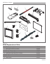
2. Follow Steps 1 through 7 in “Light Bulb Replacement” sect
ion.
3. Remove two (2) screws per side for the brackets and the fireplace screen to be
removed and set aside
.
4. Remove one (1) screw per side of the bulb housing assembly to remove and set
aside.
5. Remove four (4) screws per side for the right side cover. This allows the cover
to be opened for access to where the power cord enters the strain relief and the
compartment.
6. Using wire cutters, gently cut the power cord inside the compartment, flush to
the strain relief. Also, repeat for the power cord outside the compartment.
7. Back inside the compartment, gently separate the three (3) wires of the power
cord into separate wires by gently pulling them apart. DO NOT use a knife, as
this may expose bare conductors. The hot wire is connected to the main power
switch and is terminated with a straight terminal connector. The neutral wire is
connected at the circuit board’s screw clamp terminal block. The green ground
wire is attached to the ground stud. Use a 5/16” (8 mm) socket or wrench to
remove the brass nut, brass lock washer and brass cup washer and set aside.
Remove and discard the cut power cord ground wire.
8. Using a slotted screwdriver, remove the 7/8” (22 mm) diameter knockout above
the old power cord strain relief.
9. Route the power cable from the breaker/fuse panel through the 7/8” (22 mm)
diameter hole. Secure the cable to the compartment using an approved clamp.
The wires should extend approximately 6” (152 mm) into the compartment.
10. Connect the ground wire from the power cable by wrapping it around the ground
stud of the unit and securing it firmly with the brass cup washer, brass lock wash
-
er and brass nut.
11. Using wire strippers, strip approximately 5/8” (15 mm) from the ends of the hot
and neutral wires. Using an approved wire nut, connect the hot lead (black) of the
power cable to the power cord wire that ends at the main power switch. Similarly,
using another wire nut, connect the neutral wire (white), of the power cable to the
power cord ending at the screw clamp terminal block of the circuit board. It is rec
-
ommended that the wire nuts be taped to the wires, using electrical tape, as an
extra safety measure.
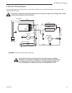
12. For extra safety measure, visually check and fix the wire routing appropriately.
Refer to the wiring diagram on the unit or in the instruction manual if any wires
have been dislodged.
13. Turn the power to the unit on at the breaker/fuse panel. Place the appliance into
operation and check to make sure all of the systems are working properly
.
WARNING: This
procedure must
be conducted by
a qualified elec
-
trician, in accordance with
National and local codes. In
the U.S.A., the installation
must conform to the National
Electrical Code, ANSI/NFPA
No. 70. In Canada, the
installation must conform
to the current CSA C22.1
Canadian Electrical Code.
WARNING: Make
sure the power to
the unit is off, and
the power cord is
unplugged from the wall out
-
let before proceeding with
this conversion. Failure to
do so may result in property
damage, personal injury or
loss of life.
WARNING: Make
sure the power to
the power cable
has been turned
off at the breaker/fuse panel
before proceeding.