


88
Dutchwest Natural Vent Gas Heater
30002008
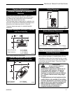
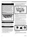
Outer
Shroud
Slot
Inner Shroud
Slot
ST194
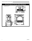
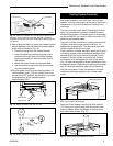
Fig. 11 Position the fan to engage the inner shroud with the
fan bracket slots and secure with sheet metal screws.
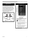
Left Air
Duct
Fan
Inner
Shroud
ST720
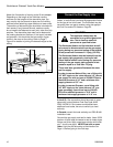
Fig. 10 Attach snapstat wire assembly to inside of inner
shroud with clamp screws.
Grommet
Front View
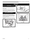
Install the Optional Fan
1. The fan kit includes a blower assembly and a
rheostat assembly, connected by a cable. The
blower assembly mounts to the bottom rear of the
stove, and the rheostat mounts to the left side of the
valve. The assembly includes a ‘snapstat’ which
automatically turns the fan ON (or OFF) above (or
below) approximately 109°F. The rheostat also
provides a range of fan speed settings from Off
(which overrides the snapstat function) to High.
Unpack and inspect the blower assembly. Confirm
that the fan spins freely.
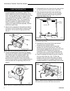
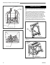
2. Attach the fan assembly to the bracket provided in
the log box. Use #10 sheet metal screws provided
with fan kit. Do not remove finger guard screws.
(Fig. 8)
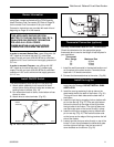
3. Connect snapstat leads. Disconnect the snapstat
module from the leads inside the snapstat bracket.
(Fig. 9) Bend open the snapstat bracket. Use
needle nose pliers to remove the black plastic
grommet from the bracket. Discard the bracket.
Connect the two wires to the two snapstat extension
leads provided with the parts bag (wires with the
sleeve).
4. Disassemble the inner shroud from the outer shroud
by removing the four screws, two on each side.
5. Place the grommet provided in the manual bag
assembly on the inner shroud. Run the snapstat
extension assembly leads through the grommet
toward the firebox. (Fig. 10)
6. Assemble the inner shroud to the outer shroud
using previously removed screws.
7. Position the fan assembly so the ducts slide
between the inner and outer shroud. The inner
shroud should engage with the two slots in the ends
of the bracket so the bracket and shroud are
interlocked. (Fig. 11) Secure the bracket with the
four sheet metal screws provided in the finish bag.
8. Install the snapstat by loosening the front screw on
the inner side of the duct. (Fig. 12) Slide the
snapstat under the head of the screw and tighten.
Connect the leads to the snapstat. Make sure the
snapstat assembly is mounted straight front to back.
Snapstat Bracket
Snapstat Module
Pinch
Grommet to
Remove
ST670
Fig. 9 Remove the snapstat and grommet from the bracket
Snapstat
Wire
Rheostat Wire
Fan
Bracket
Finger Guard
ST669
Fig. 8 Attach the fan assembly to the fan bracket.