


11
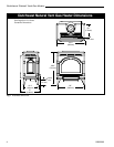
Dutchwest Natural Vent Gas Heater
30002008
Burner Information
The appliance must only use the gas specified on the
rating plate, unless converted using a CFM Specialty
Home Products Fuel Conversion Kit. Refer to Page 23
for the correct Fuel Conversion Kit for your model.
Conversion instructions are provided with each kit and
beginning on Page 16 in this manual.
THIS APPLIANCE SHOULD BE CON-
NECTED TO THE GAS SUPPLY ONLY BY A
QUALIFIED GAS SERVICE TECHNICIAN.
FOLLOW ALL LOCAL CODES.
THERE MUST BE A GAS SHUT-OFF BE-
TWEEN THE STOVE AND THE SUPPLY.
In order to connect Natural Gas, use a fitting with 3/8”
NPT nipple on the valve side and 1/2” natural gas
supply line with an input of 28,000 BTUs at a manifold
pressure of 3.5” and a minimum inlet supply pressure of
5.5” w.c.
In order to connect Propane, use a fitting with 3/8”
NPT nipple on the valve side and 1/2” propane gas
supply line with an input of 26,000 BTUs at a manifold
pressure of 10.0” and a minimum inlet supply pressure
of 11.0” w.c.
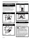
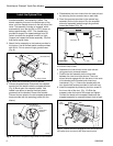
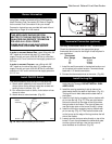
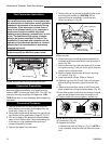
Install ON/OFF Switch
The switch assembly parts are found in the parts bag.
1. Attach switch assembly to left rear side of stove
shroud (when facing shroud) using two screws and
existing holes in shroud. (Fig. 19)
2. Run wires down back of stove, under bottom of rear
shroud to valve.
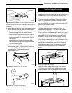
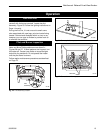
3. Attach wires to valve terminals. (Fig. 20)
Switch
Assembly
Screws
Existing
Holes
ST315
Fig. 19 Attach switch assembly to rear shroud.
PILOT
ADJ
TP
TH
TPTH
ST228
Fig. 20 Attach switch wires to valve.
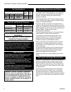
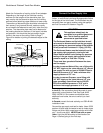
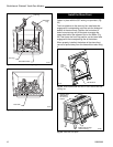
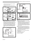
Install the Log Set
1. Remove the logs from their packaging, and inspect
each piece for damage. DO NOT INSTALL DAM-
AGED LOGS.
2. Install the rear log centering it side to side on the
sheet metal shelf at the back of the firebox. (Fig. 21)
The log will touch both sides and the back wall of
the firebox.
3. Install the right log by engaging hole on bottom with
pin on the rear log. (Fig. 21) Then set right bottom
side on the burner so the edge of the log touches
the right side of the firebox. The right log does not
use the locator pins on the burner to stay in place.
4. Install the left log by engaging hole on bottom with
pin on rear log. (Fig. 21) Then set left bottom side
on the burner so the edge of the log touches the left
side of the firebox.
5. Loosely sprinkle the lava rocks directly on top of the
burner in front of and between the decorative grate
and the right and left logs. Use the lava rock to
cover brackets on the burner. (Fig. 22)
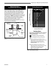
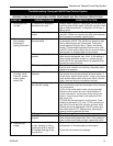
Thermostat
Wire / Gauge Maximum Run
18 40 feet
20 25 feet
22 16 feet
Thermostat Connection (optional)
Use only a thermostat rated for 500 - 750 millivolts.
Check the table below for the appropriate gauge
thermostat wire to use for the length of lead required in
your installation.
1. Install the wall thermostat in the desired location and
run the wires to the stove location. Terminate these
leads with 1/4” female connectors.
2. Connect the thermostat wires to the valve. (Fig. 20)