


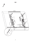

4.0. Electrical Connections
Note: Select the right electrical prong [09, 10, or 11] for your electrical socket.
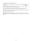
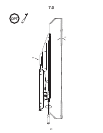
(1) Refer to Section 9.0 and manually tilt the TV up, and insert the pin [04] to the “UP” opening to hold the TV
up for easier electrical connections.
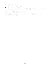
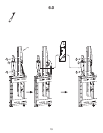
(2) Insert the AC adapter jack [06] into the control box, and plug in the electrical prong to electrical socket.
(3) Insert the IR receiver jack [07] into the control box, and attach the head of the IR receiver [07] to the bottom
of the TV. Make sure the IR receiver [07] is visible from the front of the TV.
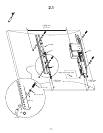
(4) Insert one end of the optical cable [08] to the control box, and the other end to the Digital Optical Audio
Output on the back of the TV. This mount system detects whether the TV is ON or OFF by detecting whether
the LED light (red) from the Digital Optical Audio Output is ON or OFF; and in Auto-Mode (refer to Section 9.0),
tilts the TV down when the LED light is ON, and returns the TV to the upright position when the LED light is
OFF.
Note: If the Digital Optical Audio Output of the TV is being used to drive speakers, then use an optical splitter
(not provided) to send signals to the control box.
Do not look into the LED light from the Digital Optical Audio Output, as this may cause temporary or
permanent injury to your eyes.
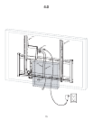
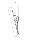
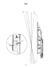
Do not run any wires and/or cables near moving parts of this mounting system. Run the cables and wires
through the shaded area as illustrated in Section 4.0 drawing.
16