


Page -5-
Clarke
®
American Sanders Operator's Manual - CAV 26
Figure 4
INTRODUCTION AND INSTRUCTIONS, cont.
1
2
3
4
Features
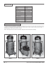
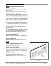
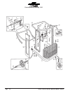
Figure 1, 1 - Control Panel
For explanation of controls, see "Controls" section this page.
Figure 1, 2 - Inlet
This inlet is for installation of vacuum hose and accessories.
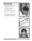
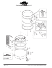
Figure 1, 3 and Figure 2, 1 - Debris Canister
The debris canister should be emptied when the canister is full.
To empty canister, lift debris canister lever (figure 3,2). Debris
canister will lower until it rests with it's wheels on the floor. Grip
the handle and remove the canister, then empty it's contents.
To fit the canister back in place, set it under the vacuum, making
sure the full sight level gauge (figure 3,1) remains visible from the
outside. Then push lever (figure 3,2) downwards, allowing the
canister to lift until it fits against filtering chamber.
Figure 1, 4 - Filter Cleaning Lever
This lever is to used to clean the filter. When manometer (figure
4, 1) reads that the filter is clogged, turn the filter cleaning lever
several times with force in order to shake the dust from the filter.
Do not operate lever with vacuum running.
Wait a few minutes for the dust to settle at the bottom of the
container, then empty.
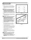
Figure 3, 1 - Full Sight Level Gauge
This gauge indicates the debris level in the debris canister (figure
1,3). The debris canister should be emptied when it is full.
Before emptying debris canister, switch off the machine by
pressing the vacuum motor switches (figure 4,2) and remove
plug from the power supply.
Figure 3, 2 - Debris Canister Lever
Lift this lever so that debris canister can be removed and emp-
tied. Make sure to lower the lever when you replace the debris
canister.
Figure 3, 3 - Balancing Hose
Balances vacuum around polytank liner (fig 2,2), so it's not
sucked into the filter.
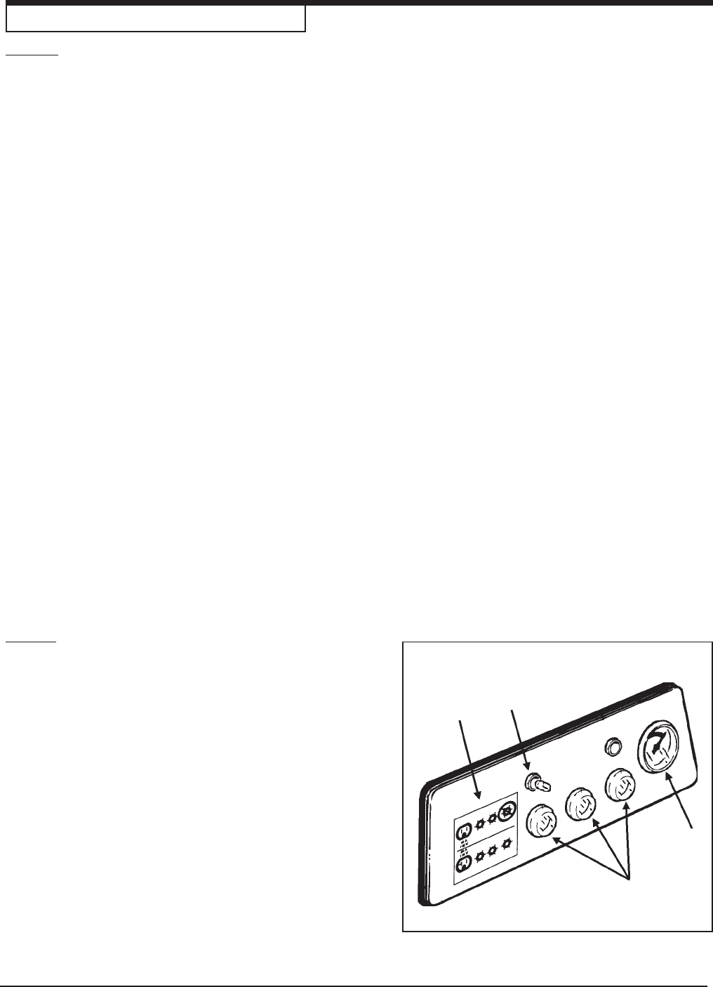
Controls
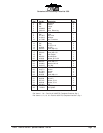
Figure 4, 1 - Manometer to display filter loading
The vacuum in the filter increases proportionally as the filter
clogs. Then the manometer needle will move from green (filter
good) to the red (filter clogged) section.
Figure 4, 2 - Vacuum Motor Switches
This model is fitted with 3 motors, so it has three vacuum motor
switches on the control panel. Press the switches to start the
vacuum motors. The warning lights (green lights) will come on.
Press the switches again to stop the motors. The warning light
will go out.
Figure 4, 3 - Electrical Label
Figure 4, 4 - Illuminated Mains Voltage Indicator
When on, this indicates that the vacuum is connected to the
electrical supply.