


Thermometer
Load (Tank, vat, die or platen)
Pilot
Light
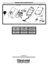
LT Models:
A. Entrance for wiring is provided by two
3
/4” NPT conduit
holes in end of housing. Wiring to control housing should
be in moisture-resistant conduit.
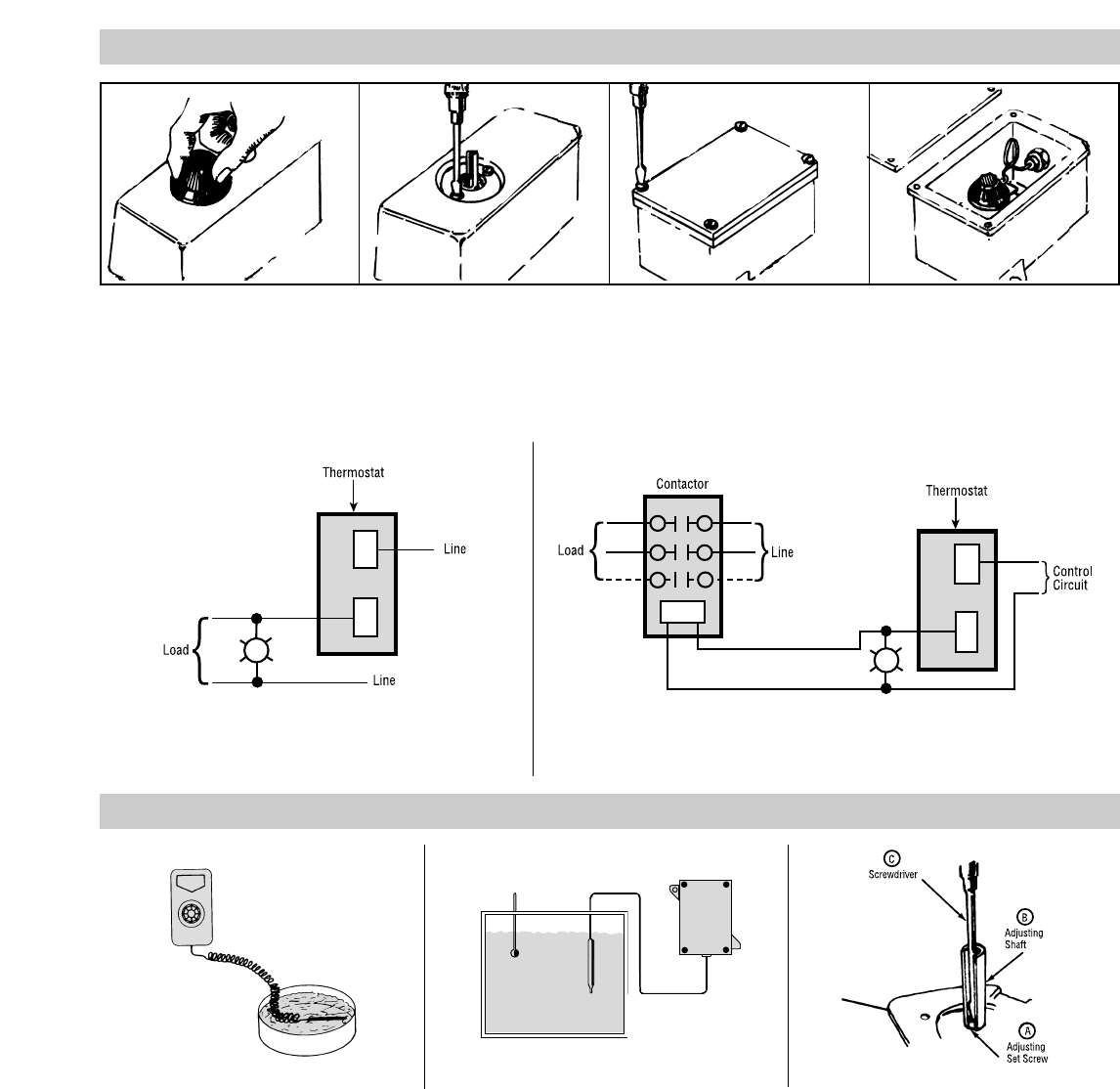
B. Remove cover by removing four hexhead screwbolts. (See
Figure 8 and 9)
2. Connect wires according to wiring diagrams (Figures 10 and
11). Note: Electrical connections should be made with gener-
ous loops of wire — approximately 6” per lead.
3. Replace cover and tighten screws.
4. Replace dial knob. (NEMA-I models only).
5. Note: If load amperage or voltage rating exceeds switch rating,
a contactor must be used. (See Figure 11) Contactors are avail-
able as an optional part.
WIRING
CALIBRATION
Pilot
Light
CAUTION: Hazard of Electric Shock. Extreme care
should be exercised during calibration adjustments
because of shock hazard due to exposed electrical
terminals.
These controls are factory calibrated to the range indicated on
the control adjustment knob.
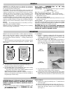
If calibration is required either one of two methods may be
followed:
1. If accurate measurement standards are not available, the ther-
mostat can readily be adjusted to a known temperature stan-
dard such as boiling water (212°F). (See Figure 12)
2. With the aid of an accurate thermometer or other temperature
measuring device, recalibration may be performed within the
process as in Figure 13.
For either method the following general calibration procedures
should be followed.
1. Remove knob and thermostat housing as per instructions under
WIRING.
2. Replace knob and turn to highest temperature setting.
3. Slowly turn knob and when controls click “off”, compare the
dial reading against the thermometer reading.
4. If they do not agree —
A. Set dial knob to thermometer temperature reading and pull
off knob.
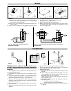
B. While holding the adjusting shaft (B) tightly, turn small
center adjusting screw (A) with small screwdriver (C) until
thermostat clicks “off”. (See Figure 14)
Note: Always use extreme care not to damage the slot in the
center adjusting screw.
C. Each quarter turn of the screw will change the calibration
approximately 30°F:
— Clockwise to decrease temperature
— Counter clockwise to increase temperature
D. Recheck calibration and repeat process if closer calibration
is required.
Figure 12
Figure 13
Figure 14
Figure 6
Figure 7
Figure 8
Figure 9
Figure 10 — Single phase loads when load does not
exceed rating of thermostat.
Figure 11 — Single phase loads when load exceeds rating of thermostat and
three phase loads.