


GENERAL
NOTICE: Type ARR Thermostats are designed for temperature
control service only. Because they do not fail safe, they should not
be used for temperature limiting duty.
CAUTION: Users should install adequate back-up controls and
safety devices with their electric heating equipment. Where the con-
sequences of failure may be severe, back-up controls are essential.
Although the safety of the installation is the responsibility of the
user, Chromalox will be glad to make equipment recommendations.
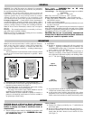
Principle of Operation — Control action of these thermostats is
provided through the principle of liquid volume change. With a
variation in temperature, the liquid in the sensing bulb expands or
contracts, causing a bellows to actuate the switching mechanism.
Note: In Inverse-Action Thermostats, contacts close on tempera-
ture rise.
Housing — The control housing and cover assembly is of heavy-
gage sheet metal on NEMA-I models.
Moisture resistant (LT) models have housing and cover assembly
made of heavy gage cast aluminum.
Power Supply — WARNING: Use on AC only.
Thermostat is not DC rated.
Control Range — The following temperature ranges are available:
Fahrenheit
60 to 250 200 to 550
Note: This control does not have an “OFF” position.
Process Temperature Differential — May be minimized by:
1. Make sure control is mounted to vertical surface. (See Step 1,
MOUNTING section)
2. Avoid excess cooling capacity.
3. Locate control sensing bulb in optimum position between cool-
ing source and work.
Packing Glands — If a sealed or leak-proof connection is required
at the point where the capillary enters the oven, tank, pipe or similar
equipment, an appropriate packing gland is available as an optional
part. (Models CCF-25A, CCF-25D or CCF-25E)
CAUTION: Not for use in hazardous environments
as described in National Electrical Code. Failure to
comply can result in explosion or fire.
WIRING
MOUNTING
Note: Do not mount control where it will be subject to vibration,
shock, grease, dust, lint or corrosive vapors. Do not mount adja-
cent to a large magnetic contactor, as vibration and shock will
cause thermostat to interact erratically — resulting in chattering of
the contactor.
The air temperature in and around the control enclosure should
be kept as near to normal room temperature as possible... never
above 150°F.
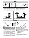
1. Thermostat must be mounted in a vertical position only.
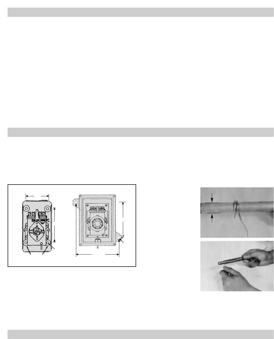
2. Use sheet metal or wood screws through the mounting holes in
baseplate to mount control. (See Figure 2)
3. For controlling platen or die temperatures, insert entire sensing
bulb into drilled holes selected for snug slip fit.
The longer, more sensitive Style 9 bulbs should be used for
controlling air temperatures or pipe line heating.
Note: If material in contact with bulb or capillary is corrosive, a
protective well should be used. Protective wells are available as
an optional part. Check Factory.
4. CAUTION —
A. Bending or deforming sensing bulb will alter control cali-
bration — requiring recalibration after installation. See
CALIBRATION section, page 3. If necessary, Style 9 bulbs
can be coiled to 1” I.D. (See Figure 3.)
B. Do not kink capillary tube. The resulting constrictions in
fluid flow can destroy control function or broaden temper-
ature differential. Minimum capillary tube bending diame-
ter is
1
/2” I.D. (See Figure 4)
C. Any deformations of bulb or capillary that result in leakage
of fluid from control renders control inoperative.
D. Avoid passing control capillary tube through zones whose
temperature is in excess of controlled process temperature.
Erratic control or destruction of control function may result.
Mounting Lugs
(2)
2 / "
7
16
3 / "
7
8
Mounting Holes
5 / " Dia.
7
8
/ " Dia.
5
16
5"
Figure 2
Figure 3
(Sensing Bulb)
Figure 4
(Capillary Tube)
CAUTION: Hazard of Electrical Shock. Disconnect
all power before wiring or servicing this control.
Failure to comply can result in electrical shock or
electrocution.
1. Electric wiring to heater must be installed in accordance with
local and National Electrical Codes. WARNING: Use cop-
per conductors only.
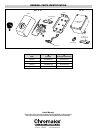
NEMA I Models:
A. Entrance for wiring is provided by two
1
/2” conduit holes in
end of base plate.
B. Remove knob by lifting knob from shaft. (See Figure 6)
C. Removal of the knob will reveal two mounting screws posi-
tioned under the knob. Remove screws and lift off cover.
(See Figure 7).
NEMA-I Models LT Models
1”
Do Not
Bend or Kink
Crimped End
1
/2”
Rod