


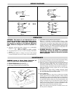

WIRING DIAGRAMS
OPERATION
WARNING: This heater is not intended for use in
hazardous atmospheres where flammable vapors,
gases, liquids or other combustible atmospheres
are present as defined in the National Electrical
Code. Failure to comply can result in explosion or
fire.
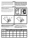
1. Minimum spacing from front of heater case to combustible
material is: 4 ft. — RBC3-12 (1200W)
7 ft. — RBC3-24 or RBC3-36 (2400W or 3600W)
2. Avoid temperatures in excess of 194˚F on nearby combustible
surfaces.
3. Do not operate heaters at voltages in excess of that stamped
on heater nameplate since excess voltage will shorten heater life.
4. CONTROLLING RADIANT INTENSITY —
When it is desirable to reduce radiant intensity, Input
Controllers may be used. These motor-driven cycling devices
can be used to vary heater output capacity from 4% to 100%.
Cycling devices are usually connected in holding coil circuit of
magnetic contactors. For further information regarding Input
Controllers and Contactors, see Chromalox catalog and/or con-
tact your local Chromalox representative.
5. WARNING: Because of the possibility of someone
unknowingly exposing the heater to combustible
hazards, the heater should not be left in operation
while unattended.
MAINTENANCE
WARNING: Hazard of Severe Shock. Disconnect all
power to heater before servicing these heaters.
A. Element Replacement (See Figure E)
1. Remove Terminal housing cover and gasket.
2. Disconnect element leads from external leads.
3. Loosen and disengage hex nut and washer from threaded fitting.
4. Pull element out of reflector housing and terminal box.
5. Slide new gasket (see Renewal Parts) onto threaded fitting of
replacement element. Note: Filler side of gasket faces away
from flange of threaded fitting. Insert new element through ter-
minal box opening, and slip on washer and hex nut before ele-
ment enters reflector housing. Tighten hex nut until element
mounting is secure.
6. Reconnect power supply leads to element terminals. Install
new terminal cover gasket (see Renewal Parts). Install terminal
box cover. Reconnect power to heater circuit.
B. Care of Reflector
The reflectors should be kept clean to obtain the maximum
radiant output. The entire assembly should be washed or brushed
off periodically to remove dust and dirt. However, if the inside of
the reflector gets badly soiled, a mild soap and water solution may
be used. Wipe reflecting surface dry to prevent permanent water
marks. For extreme cases of soil which do not yield to mild soap
cleaning, use plastic or fine steel wool type scouring pads com-
monly used on cooking utensils. Avoid use of ammonia or alka-
line cleaners which will etch the aluminum surfaces.
Note: Avoid hosing down the heater assembly because con-
duit may not be waterproof.
Figure 1
Figure 2
Figure 4
Figure E
L1
L2
Ground (Green)
G
Ground (Green)
G
L1
L2
Ground (Green)
G
L3
L1
L2
Figure 3
For supply connections use wire suitable for at least 90˚C (see below)
For supply connection use 14GA. min. wire suitable for at least 75˚C.
For supply connection use 14GA. min. wire suitable for at least 90˚C.
Ground (Green)
G
L1
L2
For supply connection use 14GA. min. wire suitable for at least 90˚C.
208V 10GA. min.
240V 12GA. min.
480V 14GA. min.
Terminal Box
Hex Nut
Washer
Compression
Gasket
Grounding
Terminal
Threaded
Fitting