


GENERAL
The Chromalox Type RBC-3 Radiant Heater is designed primar-
ily as an indoor comfort heater to be used where supplemental heat is
needed or for spot heating in unheated areas and damp locations.
Its aluminum construction and consequent light weight make it
ideal for suspension with the No. 2 size chain and “S” hooks pro-
vided. Aluminum reflector housing requires no painting and is eas-
ily cleaned.
WARNING: Users should install adequate controls
and safety devices with their electric heating
equipment. Where the consequences of failure may
be severe, back-up controls are essential.
Although the safety of the installation is the
responsibility of the user, Chromalox will be glad to
assist in making equipment recommendations.
WIRING
WARNING: Hazard of Electric Shock. Any installation
involving electric heaters must be effectively
grounded in accordance with the National Electrical
Code to eliminate shock hazard.
Electric wiring to heater must be installed in accordance with
the National Electrical Code and with local codes by a qualified
person. WARNING: Use copper conductors only.
WARNING: To prevent electrical wiring problems
due to overheating, route wiring conduit to avoid
contact with reflector housing.
MOUNTING
WARNING: Hazard of Electric Shock. Disconnect all
power before installing heater.
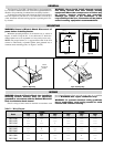
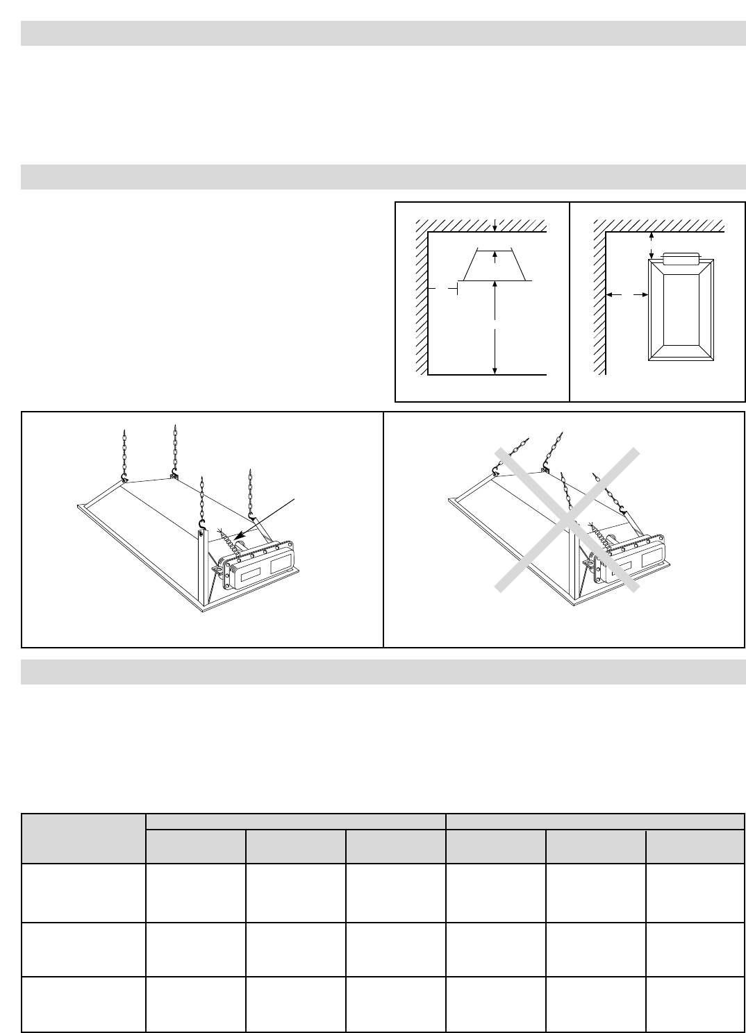
Minimum mounting distances for all heaters are as shown in
Figures A and B. Using the No. 2 size chain and “S” hooks fur-
nished, heaters are to be suspended in a horizontal position only.
NOTE: For proper balance, it is suggested that each of the four
corners be individually suspended (rather than gathered into a
common center mounting point, see Figure C and D).
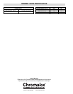
Model 208V 240V 480V 208V 240V 480V
Fig. Fig. Fig. Fig. Fig. Fig.
RBC-31280 1 —— —— —— —— ——
RBC-31220 —— 1 —— —— —— ——
RBC-31240 —— —— 1 —— —— ——
RBC-32480 2 —— —— —— —— ——
RBC-32420 —— 2 —— —— —— ——
RBC-32440 —— —— 2 —— —— ——
RBC-33680 3 —— —— 4 —— ——
RBC-33620 —— 3 —— —— 4 ——
RBC-33640 —— —— 3 —— —— 4
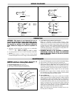
Table B — Wiring Diagram
Figure A
Figure B
Figure D (Wrong Way)Figure C (Right Way)
4" Min.
72" Min.
14"
Min.
Ceiling
Wall
Floor
Wall
Wall
14"
Min.
9" Min.
Conduit
Furnished by
Installer
1 Phase
3 Phase