


MAINTENANCE
ELECTRIC SHOCK HAZARD. Disconnect all power
before installing or servicing heater. Failure to do
so could result in personal injury or property dam-
age. Heater must be installed or serviced by a qual-
ified person in accordance with the National
Electrical Code, NFPA 70.
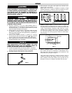
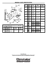
A. To Remove Heating Element —
1. Remove element assembly mounting nut and bolt and and
element support clips (see Figure 8) and slide element assembly out
of housing.
2. Disconnect heating element from electrical leads at both ends.
3. Remove screws from porcelain terminal blocks.
4. Remove element support clips and secondary insulating
bushings.
5. Lift element out of heater.
B. To Install Element —
Observe instructions for removing element and proceed in
reverse fashion. Be sure to replace secondary insulating bushings.
C. Care of Reflectors —
Reflectors should be cleaned periodically. A mild soap and
water solution or fine cleaning powder is best although more
drastic means may be required if reflectors are badly soiled by
chemical or other deposits. The reflector is aluminum. DO NOT
use alkali cleaners since alkalies will dull reflector. Mild non-
alkaline cleaners, such as used for scouring kitchen sinks, may
be used. Reflectors are replaceable and may be purchased from
Chromalox.
18 16
OPERATION
FIRE/EXPOSION HAZARD. This heater is not
intended for use in hazardous atmospheres where
flammable vapors, gases, liquids or other com-
bustible atmospheres are present as defined in the
National Electrical Code. Failure to comply can
result in personal injury or property damage.
Before energizing this heater:
1. Be sure all electrical connections are tightly made. Hold ter-
minal with pliers when tightening screw.
2. Be sure that all conductors are properly insulated.
3. Be sure that all element assemblies have been properly
replaced, and that secondary insulation bushings have not been
omitted.
A. Controlling Radiant Intensity —
Standard Radiant Heaters are built to operate at approximately
40 watts per sq. inch on the element sheath. When it is desired
to reduce radiant intensity, one or more of the following meth-
ods may be used.
1. INPUT CONTROLLERS. These motor-driven cycling
devices can be used to vary heater output capacity from 4 to
100%. They are usually connected in holding coil circuit of
magnetic contactors. See Chromalox Radiant Heater Manual
for further information regarding Input Controllers and
Contactors.
2. SOLID STATE THYRISTOR POWER CON-
TROLLERS.
For best non-contact control of radiant heat, a Series #6
Chromalox Thyristor Power Controller with manual poten-
tiometer setting is recommended. Truly proportional output
of from 0-100% can be easily dialed-in to suit the particular
product or process requirements. The Series #6 panels are
pre-engineered, pre-packaged assemblies in an enclosure
with circuit disconnect provided and ready for installation.
B. Maximum Ambient Temperatures —
CHROMALOX Radiant Heaters are not recommended for
applications in ambient temperature exceeding 450˚F. Higher
ambient temperatures mean shorter heater life.
Maximum work temperature in a given time depends on sever-
al factors: Reflectivity of work, specific heat of work, mass of
work, kW input and losses from oven, and time of exposure. As
work temperature increases, the work loses heat by radiation and
by convection to the surrounding ambient. Although it is a gen-
eral principle of Radiant Heater application that work tempera-
ture conventionally exceeds ambient temperature, in cases
where extremely high work temperatures are desired, it is nec-
essary to enclose the heaters in order to increase the ambient. If
evaporation of a liquid is desired as a result of increasing work
temperature, it is necessary to provide ventilation air in order to
carry away the evaporated liquid. Under carefully engineered
circumstances, a maximum work temperature of 600˚F may be
attained.