


INSTALLATION
ELECTRIC SHOCK HAZARD. Disconnect all power
before installing or servicing heater. Failure to do
so could result in personal injury or property dam-
age. Heater must be installed or serviced by a qual-
ified person in accordance with the National
Electrical Code, NFPA 70.
Mounting
1. These radiant heaters are designed for indoor installation only.
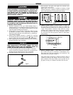
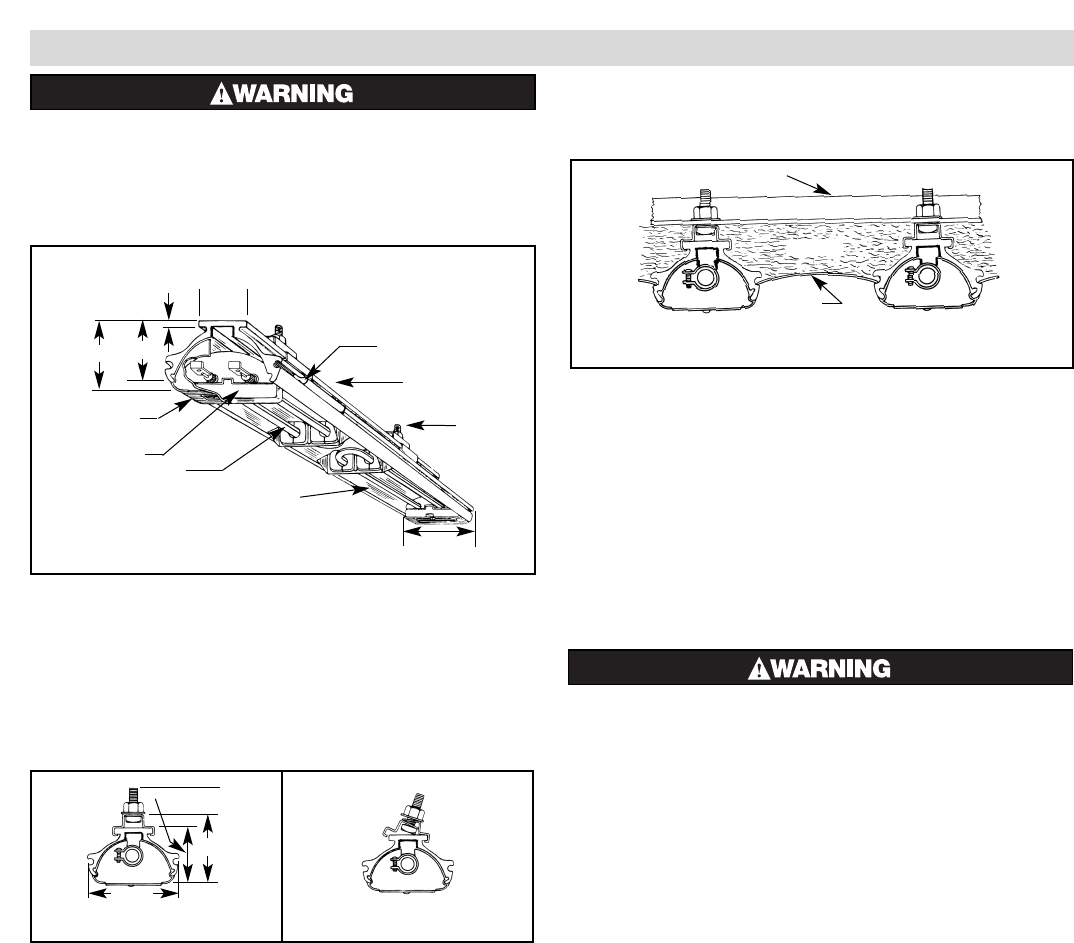
2. Clamps — Heaters are mounted by means of the mounting
clamp and 3/8” bolt assembly which is used as shown in Fig. 2.
Clamp assembly may be attached to heater by sliding over end
or by snapping over top of extruded frame section at any point
along its length (see Fig. 3). For proper heater support, the max-
imum distance between clamps must not exceed 48”. On extra-
long heaters, more than two clamps are furnished.
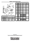
3. Mounting Holes — When heaters are mounted adjacent to
each other in the same plane, note that distance between mounting
holes on framing to support heaters will be 3-11/16”minimum.
When heaters are not in the same plane, i.e. set at an angle to one
another, distance between mounting holes in framing will be either
greater or less than 3-11/16”.
4. Framing — Where an extensive installation is being made,
the use of continuous slot metal framing manufactured by sev-
eral concerns will be of assistance in saving time and money.
The frame is reusable.
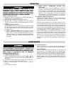
5. Reflector Spacer Sheets — Where heaters are not mounted
side by side (see Fig. 4), reflector spacer sheets can be used
between heaters. These reflector spacer sheets and companion
reflectors consisting of an extruded aluminum housing with
reflector sheet and mounting clamps are available. Check with
local sales representative.
6. Insulation — Where unusually high work temperatures are
encountered, it may be desirable to insulate backs of heaters
with high-temperature fibrous insulation. A suggested method
of accomplishing this is indicated in Fig. 4.
7. Ventilation — Where solvents, water, etc. are being evaporat-
ed from work in process, it is necessary to provide substantial
quantities of ventilation air to carry away the resulting vapors.
FIRE HAZARD. Since Radiant heaters are capable
of developing high temperatures, extreme care
should be taken to:
A. Keep combustible materials at least 6” away
form sides and back of heater housing and its sup-
porting brackets and spaced far enough in front of
heater (heating element side) so thermal radiation
from the elements will not ignite combustible
materials.
B. If combustible materials are being processed,
stoppage of process should initiate immediate
heater shutdown and interception of residual heat
from radiant heaters (use radiation baffles or move
heaters away from work).
C. In the case of solvents of an explosive nature,
ventilation air must be in sufficient volume to
dilute the solvent vapor so that explosive mixtures
cannot occur, refer to NFPA 86, Standard for Ovens
and Furnaces.
Figure 4
Insulation
Reflector
Spacer Sheet
Mounting Frame
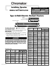
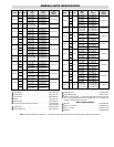
Figure 1 — Heater Parts and Dimensions
Terminal Cover
Terminal Block
Element
Polished Aluminum Reflector
Interlocking Connector
Housing
Mounting
Clamp
Assembly
2-3/8”
3-11/16”
1/4”
1-7/8”
Figure 3
2-3/8”
2-15/16”
3-
Figure 2