


5
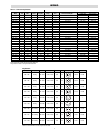
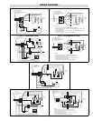
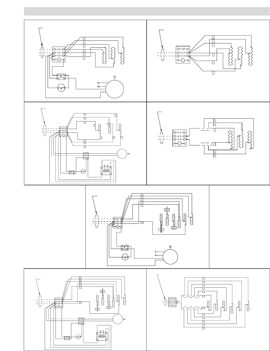
WIRING DIAGRAMS
T3
T2
T1
L3
L2
L1
2
1
3
Thermostat
Cord by others.
Type "SO" or equal
sized to meet nameplate
requirements
4
1
3
5
6
Front of
Heater
6
5
4
3
2
1
Red
Motor
Blu
Blk
Wht
Cutout
6
4
T2
T1
L2
L1
2
Cord by others.
Type "SO" or equal
sized to meet nameplate
requirements
4
1
3
5
6
Front of
Heater
6
5
4
3
2
1
All control wiring
same as Diag. 1
Instructions:
1. Loosen screws on load side of contactor. Remove all lead wire.
2. Insert lead wires numbers 1, 3, and 5 into box lug connector "T1". Tighten screws
on box lug connector.
3. Insert lead wires numbers 2, 4, and 6 into box lug connector "T2". Tighten screws
on box lug connector.
4. Examine wiring to make certain it is per above diagram.
T3
T2
T1
L3
L2
L1
2
1
3
Thermostat
Cord by others.
Type "SO" or equal
sized to meet nameplate
requirements
4
1
3
5
6
Front of
Heater
6
5
4
3
2
1
Blk/Red or Grey
Motor
Blk
Wht
Cutout
6
4
Contactor
1
3
5
2
4
6
To T3
To T3
To T1 To T2
To T1
To T2
Fan Relay
A2
T2
T1
A1
L2
L1
XFMR
Blk
Black
White
All control wiring
same as Diag. 2
T2
T1
L2
L1
2
Cord by others.
Type "SO" or equal
sized to meet nameplate
requirements
4
1
3
5
6
Front of
Heater
6
5
4
3
2
1
All even numbered wires to T2
All odd numbered wires to T1
Contactor
Instructions:
1. Loosen screws on load side of contactor. Remove all lead wire.
2. Insert lead wires numbers 1, 3, and 5 into box lug connector "T1".
Tighten screws on box lug connector.
3. Insert lead wires numbers 2, 4, and 6 into box lug connector "T2".
Tighten screws on box lug connector.
4. Examine wiring to make certain it is per above diagram.
T3
T2
T1
L3
L2
L1
11
1
3
Thermostat
Cord by others.
Type "SO" or equal
sized to meet nameplate
requirements
9
10
7
8
12
Front of
Heater
10
9
4
3
2
1
Blk/Red or Grey
Motor
Blk
Wht
Cutout
6
4
Contactor
1
3
5
2
4
6
To T3
To T3
To T1
To T2
To T1
To T2
Fan Relay
A2
T2
T1
A1
L2
L1
XFMR
Blk
Black
White
6
5
12
11
8
7
10
4
12
9
8
11
10
9
4
3
2
1
All control wiring
same as Diag. 4
T2
T1
L2
L1
Cord by others.
Type "SO" or equal
sized to meet nameplate
requirements
Front of
Heater
All even numbered wires to T2
All odd numbered wires to T1
Contactor
Instructions:
1. Loosen screws on load side of contactor. Remove all lead wire.
2. Insert lead wires numbers 1, 3, 5, 7, 9 and 11 into box lug connector "T1".
Tighten screws on box lug connector.
3. Insert lead wires numbers 2, 4, 6, 8, 10 and 12 into box lug connector "T2".
Tighten screws on box lug connector.
4. Examine wiring to make certain it is per above diagram.
1
3
5
2
7
6
6
5
12
11
8
7
T3
T2
T1
L3
L2
L1
11
1
3
Thermostat
Cord by others.
Type "SO" or equal
sized to meet nameplate
requirements
9
10
7
8
12
Front of
Heater
10
9
4
3
2
1
Motor
Blue
Cutout
6
4
Contactor
1
3
5
2
4
6
To T3
To T3
To T1
To T2
To T1
To T2
Red
Black
White
6
5
12
11
8
7
Diag. 1 – FACTORY WIRED 3 PHASE Diag. 1a – FIELD CONVERSION TO 1 PHASE
Diag. 2 – FACTORY WIRED 3 PHASE Diag. 2a – FIELD CONVERSION TO 1 PHASE
Diag. 3 – FACTORY WIRED 3 PHASE
Diag. 4 – FACTORY WIRED 3 PHASE
Diag. 4a – FIELD CONVERSION TO 1 PHASE