


4
Cord Preparation for Chromalox Portable Heaters
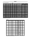
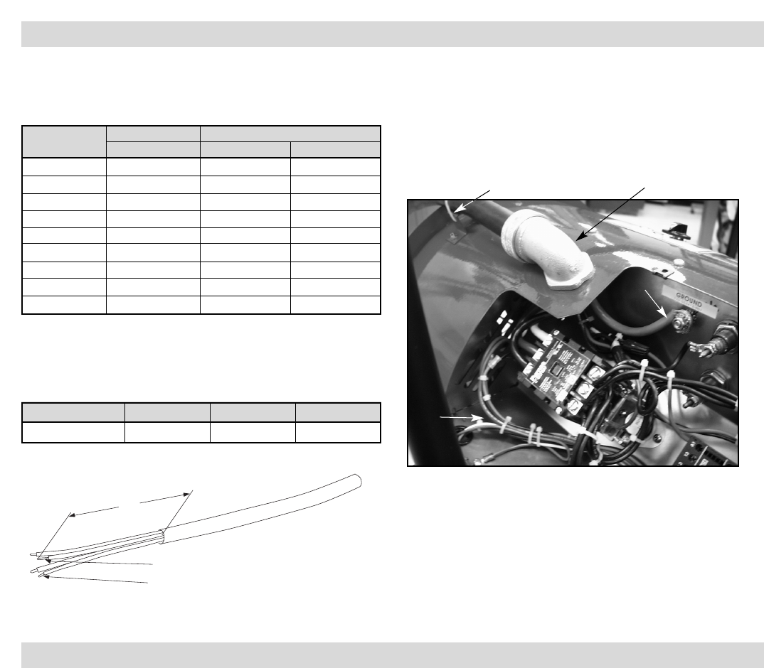
1. Determine the gage and number of conductors from the tabu-
lation below using amps and phase from the heater nameplate.
It is not recommended that cord exceed 50 feet in length.
*Includes 90 degree fitting and 25 foot of cord, reducers and locknut
2. Strip off outer jacket of cord and insulation from lead wires.
The tabulation below provides the strip dimensions for the var-
ious Chromalox portable heaters. See the nameplate on the
heater for the Model number.
3. Slide fitting onto cord and tighten knurled nut to secure fitting
to cord.
4. Select plug to match electrical rating of cord.
5. On opposite end of cord prepare end as directed by instructions
that are provided with the plug.
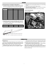
6. Attach cord assembly to heater as shown in Fig. 2 below:
WIRING
OPERATION
THERMOSTAT
Heaters include a bimetal thermostat for the automatic control
of the exiting air temperature. The thermostat knob controls the
heating elements and fan functions. The heater and fan are de-
energized with the knob in the extreme clockwise position.
Turning the knob clockwise from the off position to the fan
position will energize the fan only, for use in summer cooling.
The adjustment knob controls power to the heater and fan when
turned further in the clockwise direction, with the highest tempera-
ture setting in the extreme clockwise position.
The temperature setting in the heater mode is approximately
40°F in the low setting and 100°F at the highest setting.
Note: The adjustment knob should be turned to the fan only set-
ting after use for heating. The fan should be left on for at least 3
minutes to remove residual heat from the unit and to prevent over-
heating of the housing.
Max. Heater Amps
Chromalox Cord Kit* Cord Ga/No. Cond. and Type
Model No. 1 Phase 3 Phase
15 PLC-2514-4 14/4 SO
20 PLC-2512-4 12/4 SO
30 PLC-2510-3 10/3 SO
25 PLC-2510-4 10/4 SO
40 PLC-2508-3 8/3 SO
35 PLC-2508-4 8/4 SO
55 PLC-2506-3 6/3 SO
45 PLC-2506-4 6/4 SO
60 PLC-2504-4 4/4 SO
Model No. A B C
DRA - (all suffixes) 8” 1” 0.5”
"A"
"B" (Insulation strip dimension for ground wire).
"C" (Insulation strip dimension for power wires).
Figure 2
Run wire tie through slots in bracket
and over cord. Pull tab of wire tie to
provide cord strain relief.
Power
wires
Ground
wire
90° fitting