


3
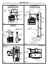
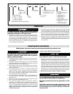
The heaters may be mounted at any convenient height above
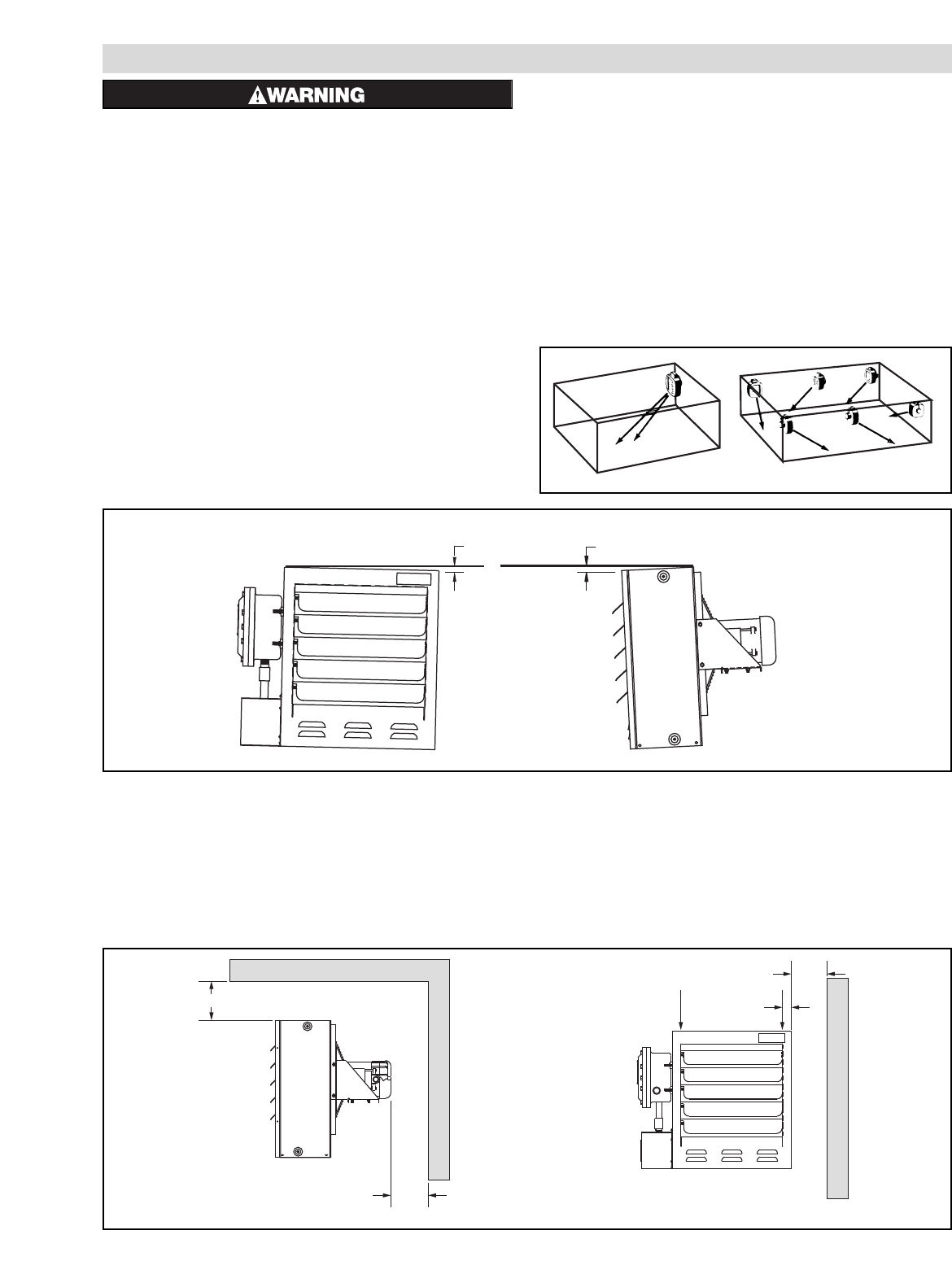
floor. The minimum spacings shown in Figure 4 should be main-
tained to adjacent walls and ceiling. If floor heat is desired, do not
mount higher than 8 to 10 feet above floor.
Controlling thermostats to individual heaters should be
mounted at shoulder height on inside walls or columns and clear
of the discharge air stream of the unit. Allow at least 4 in front of
heater for air stream to discharge freely.
Do not mount mercury type thermostat directly on unit,
vibration could cause malfunction.
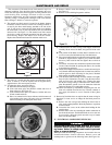
Heater may be mounted on a shelf or stand from the bottom.
Be sure that mounting clearances are maintained and that bottom
of unit has at least 1 clearance underneath it. This is necessary for
good air circulation and servicing of heat exchanger. All mount-
ing methods must allow for removal of front cover.
The mounting and anchoring provisions must take into
account the unit vibration and cantilevered loading when wall or
pole mounted. One of the Chromalox mounting kits shown in
Figures 5, 6 and 7 must be used whenever possible.
INSTALLATION
FIRE/EXPLOSION HAZARD. Mount only in upright
position and observe nameplate mounting clear-
ances.
Heater Location instructions:
Arrange units so their discharge air streams:
A. are subjected to a minimum of interference from columns,
machinery and partitions.
B. wipe exposed walls without blowing directly at them.
C. are directed away from room occupants in comfort heating.
D. are directed along the windward side when installed in a
building exposed to a prevailing wind.
Locate thermostat on interior partition walls or posts away
from cold drafts, internal heat sources and away from heater dis-
charge air streams.
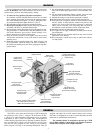
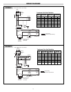
Small rooms can be heated by one unit heater. Where two
walls are exposed, the heater should be mounted as shown in
Figure 2. Large rooms require multi-unit installations. Number
and capacity of units will be determined by volume of building
and square feet of floor area to be heated. Arrange units to pro-
vide perimeter air circulation where each unit supports the air
stream from another.
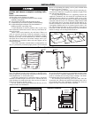
The CXH-A hazardous location heaters are designed for use
only in a permanently mounted upright position. We recommend
the use of a mounting kit (ceiling, wall or pole) available from
Chromalox. (Figures 5, 6 and 7)
The ceiling or wall mounting surface and the anchoring pro-
vision must be sufficient to support the combined weights of the
unit and mounting hardware.
If using mounting hardware or a supporting structure not
supplied by Chromalox, the unit should be suspended from the
supporting structure thru the two mounting points on top of the
unit with 5/8 NC bolts and lockwashers. If single point mounting
is desired, order the correct size Chromalox adapter bracket (P/N
027-302361-001 for 12” fan units, P/N 027-302361-002 for 16”
fan units) and P/N 027-302361-003 for 20” fan units. This bracket
is designed to hold the unit over its center of gravity with a 1 dia.
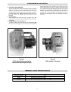
bolt. The maximum tilt angles as shown in Figure 3 must not be
exceeded in either direction during operation and installation.
Failure to comply will cause high limit shut down.
1/2" Max
13mm
1/2" Max
13mm
102mm Min. (4")
204mm
Min.
(8")
102mm
Min.
(4")
2"
5/8 NC (2)
Thds. For
Mounting
Figure 3
Maximum Out of Plane Allowance
Installation Clearances
Figure 4
EXPOSED
EXPOSED
EXPOSED
EXPOSED
EXPOSED
EXPOSED
Figure 2