


4
WIRING
ELECTRIC SHOCK HAZARD. Disconnect all power
before installing or servicing heater. Failure to do
so could result in personal injury or property dam-
age. Heater must be installed by a qualified person
in accordance with the National Electrical Code,
NFPA 70.
ELECTRIC SHOCK HAZARD. Any installation involv-
ing electric heaters must be performed by a quali-
fied person and must be effectively grounded in
accordance with the National Electrical Code to
eliminate shock hazard.
1. Use heater only on the voltage and frequency specified on the
nameplate.
2. All wiring should be done in accordance with local codes and
the National Electrical Code by a qualified person as defined in
the NEC.
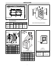
3. Two knockouts are provided on the back of the heater for wire
entry. See Figure 6 for location of knockouts.
4. Branch circuit wire for connection to heater must be at least
60°C wire.
5. The bottom access door is hinged. There is one screw that must
be loosened to gain access (Figure 3). This screw is the captive
type; do not try to remove it.
6. A ground terminal is provided near the power terminal board.
The ground wire should be connected before other connections
are made.
7. Stripped wire leads are supplied to be connected to accept the
correct size power supply wire. Copper wire rated at 600V and
60°C is satisfactory for the heater branch circuit.
8. Electrical accessories, either kits or factory-installed options, are
shown connected by a dash line on the heater wiring diagram.
9. Wiring connections are to be made on designated wire leads as
shown in the wiring diagrams located inside the access door.
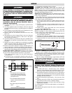
POWER DISCONNECT SWITCH (Available as a kit or factory
installed option.) This switch (Figure 7) disconnects the power to
the power leads when the handle is placed in its off position.
1. Use copper conductor supply wire only when connecting to
the power line.
2. Connection to the switch pigtails should be made with com-
pression connectors and the joint should be then well insulated.
3. Consult the local wiring code in your area.
SUMMER FAN SWITCH (MOUNTED ON FRONT OF
HEATER). When the switch handle is pointing toward the “SUM-
MER” position, the fan will run continuously. When the switch
handle is pointing toward the “WINTER” position, the fan will run
only when the heating elements are hot.
REMOTE FAN SWITCH (MANUAL SWITCH-LINE VOLT-
AGE). 480V requires an additional relay. The wall switch is packed
in the wiring compartment.
The remote fan switch is mounted external and remote from the
LUH unit heater. The voltage of the remote fan switch is the same
as the supply voltage to the LUH heater.
1. Use 14 gauge copper, NEC Class 1, 600V rated insulated wire.
Wiring must meet all Local and NEC requirements for 480V
service.
2. Install the remote fan switch in standard wall box in any con-
venient location that is protected from traffic or other acci-
dental damage.
3. Connect the 14 gauge copper field wire to the switch lead
wires with suitable connectors.
REMOTE FAN SWITCH (USED WITH 24 or 120-VOLT
RELAY) (Available as a kit or factory installed option). The wall
switch is packed in the wiring compartment.
1. Use 18 gauge (min.) NEC Class 1, 600V wiring that meets all
Local and NEC requirements.
2. Install the wall switch in a standard wall box in any convenient
location that is protected from traffic or other accidental damage.
3. Connect the field wire to the switch lead wires with suitable
connectors.
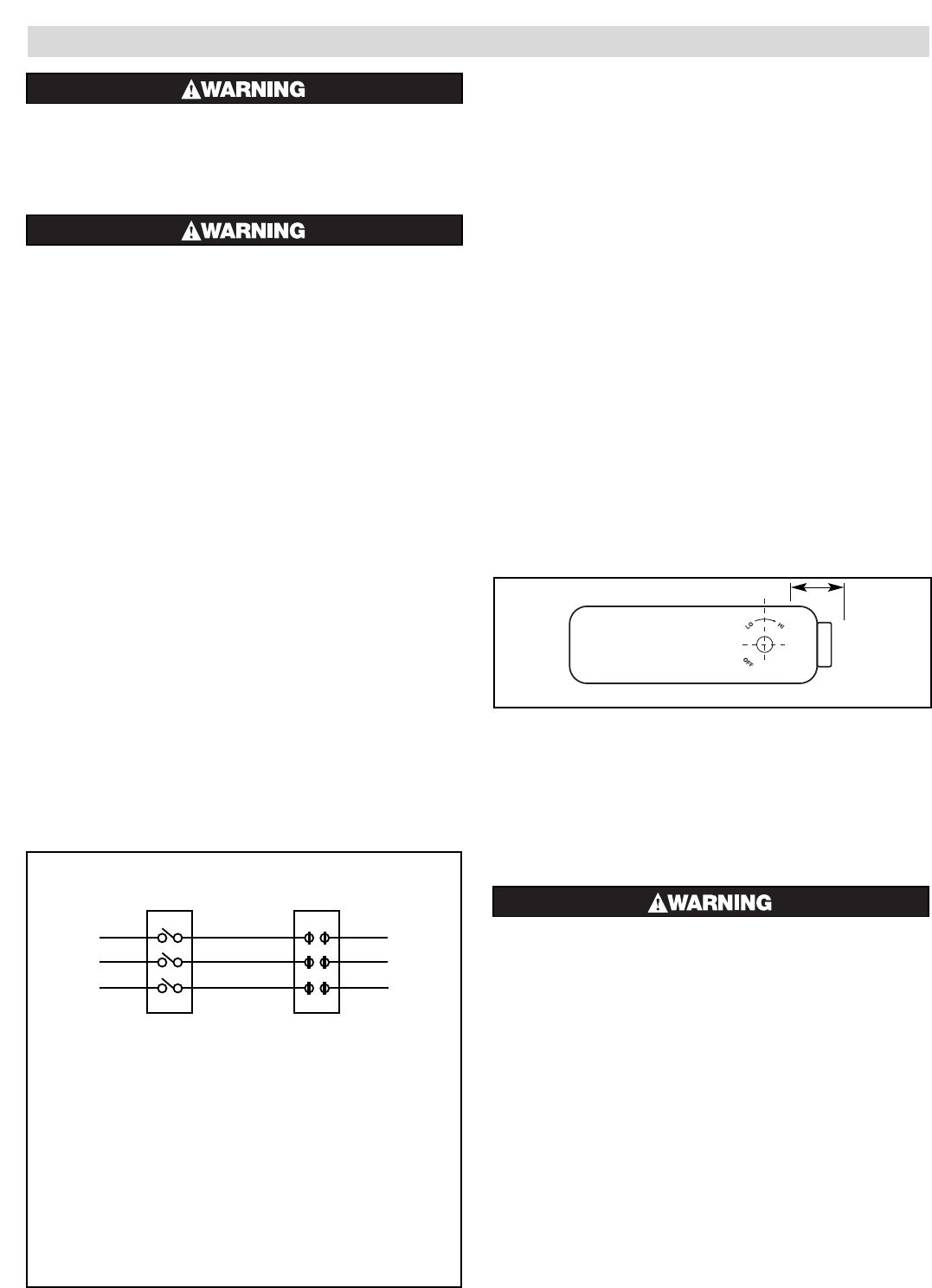
OPTIONAL THERMOSTAT (LUH-TK)
Heaters can be equipped with an optional thermostat of the
Bulb and Capillary type for automatic temperature control (Figure
8). The thermostat controls the heating elements and fan simulta-
neously to achieve set temperature.
The “Lo” setting of the thermostat is approximately 40°F, and
the “Hi” setting is approximately 90°F.
CONTROL VOLTAGE WIRING - EXTERNAL REMOTE
THERMOSTATS AND FAN SWITCHES
ELECTRIC SHOCK HAZARD. Line voltage is present
on some of the terminals. Always disconnect the
power from the heater before making any connec-
tions.
1. Use 600V, NEC Class 1 insulated wiring with a minimum
gauge of 18 for thermostats and a minimum gauge of 14 for
line voltage motor switch (remote fan switch without relay).
2. The thermostat should be located in the area to be heated on
an inside wall. The thermostat should not be exposed to drafts,
sunlight, radiation from hot objects, or in a direct line with the
discharge from the unit heater.
3. Install the thermostat approximately 5 feet above the floor
line.
4. Install the remote fan switch in any convenient location that is
protected from traffic or likely accidental damage.
5. Internal optional controls are shown on the unit heater wiring
diagrams by a dash line.
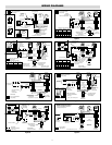
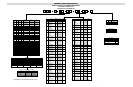
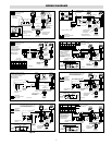
Use wiring diagrams as listed for model number on (A through X),
pages 5, 6 and 9.
For installation and optional control kits, refer to instruction sheets
listed on page 8.
Chromalox
®
Figure 8 — Thermostat Location, Front View
Power
Disconnect
Switch
L1
L2
L3
S1
S2
S3
See Notes
Contactor
To
Power
Supply
See
Note 2
Notes:
1. This illustration shows wiring hook up
for three phase service. Remove lead
wires marked L2 and S2 when using single
phase power service.
2. For units without contactors, disconnect
switch is to be wired to lead wires on
heater power.
3. Use copper supply wire only with this
switch.
Figure 7
Power Disconnect Switch Wiring Diagram
15/16”