


Please read all of the following instructions:
Failure to observe these precautions could result
in personal injury or equipment damage.
1. The heater must be mounted at least 7’ above the floor to pre-
vent accidental contact with the heating elements or fan blade
which could cause injury.
2. Keep at least 5’ clearance in front of heater. Refer to Table 2 for
side, top and back clearance requirements.
Clearance Requirements — Table 2
3. The ceiling mounting structure and the anchoring provisions
must be sufficient to support the combined weight of the heater
and mounting bracket. (Refer to Table 3 for weights of heater
and bracket.)
4. The wall or mounting surface and the anchoring provisions
must be capable of supporting the combined weight of the
heater and mounting brackets cantilevered from the mounting
surface. (Refer to Table 3 for weights of heater and brackets and
for cantilevered force expressed in foot-pounds.)
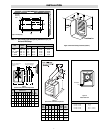
The heater may be mounted either on the ceiling or on the wall
as follows:
A. CEILING. The ceiling mounting bracket is fastened to the top
of the heater using the four bolts supplied with the mounting
bracket. The bracket is then mounted to the ceiling using a 5/8”
bolt (supplied by others).
CEILING (Alternate)
1. The heater can be rod mounted to the ceiling by installing
four threaded mounting rods in the threaded holes located on
the top of the heater as shown in Figure 2. (Refer to Table 4
for mounting rod thread size.)
2. Securely attach the four mounting rods to the ceiling. (Refer
to Table 2 for wall and ceiling clearances, and Figure 3 for
mounting spacing specifications).
B. WALL. Wall mounting kits include both a ceiling mounting
bracket and a wall mounting bracket. First, attach the ceiling
mounting bracket to the heater as described in step 4A. Then
attach the wall mounting bracket to the wall using four 3/8” bolts
(supplied by others). Attach the ceiling mounting bracket on the
heater to the wall mounting bracket using the 5/8” bolt provided.
The heater may be rotated to discharge in the desired direction.
Open and adjust louvers to desired position. See Figure 4 and 5 for
additional mounting details.
Heater & Bracket Weights Combined — Table 3
Mounting Limitations (In.)
Back Side Top to
Basic Model to Wall to Wall Ceiling
LUH-02 through LUH-05 6 6 4
LUH-07 through LUH-15 6 6 6
LUH-20 and LUH-25 6 6 6
LUH-30 through LUH-45 6 6 6
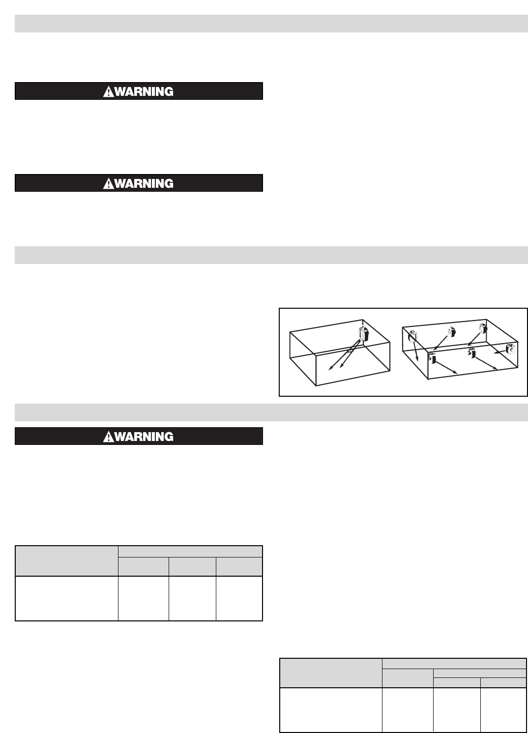
Heater Location Instructions:
Arrange units so their discharge air streams:
A. are subjected to a minimum of interference from columns,
machinery and partitions.
B. wipe exposed walls without blowing directly at them.
C. are directed away from room occupants in comfort heating.
D. are directed along the windward side when installed in a build-
ing exposed to a prevailing wind.
Locate thermostat on interior partition walls or posts away
from cold drafts, internal heat sources and away from heater dis-
charge air streams.
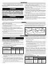
Small rooms can be heated by one unit heater. Where two walls
are exposed, the heater should be mounted as shown in Figure 1.
Large rooms require multi-unit installation. Number and capac-
ity of units will be determined by volume of building and square feet
of floor area to be heated. Arrange units to provide perimeter air cir-
culation where each unit supports the air stream from another.
2
IMPORTANT
Failure to understand and follow these installation instruc-
tions and the “WARNING” notes therein may result in serious per-
sonal injury from electrical shock, or from the heater failing due to
faulty installation.
FIRE/EXPLOSION HAZARD. This heater is not intended
for use in hazardous atmospheres where flammable
vapors, gases, liquids or other combustible atmos-
pheres are present as defined in the National Electrical
Code. Failure to comply can result in personal injury,
explosion or fire. For these applications see PDS CXH-
A-EP (PF490).
Users should install adequate back-up controls and
safety devices with their electric heating equipment.
Where the consequenses of failure may be severe,
back-up controls are essential.
Do not mount mercury type thermostat directly on unit.
Vibration could cause heater to malfunction.
The heater must be mounted at least 7' above the floor to pre-
vent accidental contact with the heating elements or fan blade
which could cause injury.
Keep at least 5' clearance in front of the heater. Refer to Table
2 for side, top and back clearance requirements.
The ceiling mounting structure and the anchoring provisions
must be of sufficient strength to support the combined weight of the
heater and mounting bracket. (Refer to Table 3 for weights of
heater and bracket.)
The wall or mounting surface, and the anchoring provisions
must be capable of supporting the combined weight of the heater
and mounting brackets cantilevered from the mounting surface.
(Refer to Table 3 for weights of heater and brackets and for can-
tilevered force expressed in foot-pounds.)
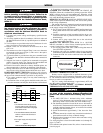
Fan blade rotation must be checked. If airflow is not moving
out through the louvers, interchange any two of the three customer
power leads on three-phase units only.
GENERAL
INSTALLATION
Figure 1
Weight (Lbs.) Heater and Brackets
Heater Ceiling Wall
Model Weight Weight Ft./Lbs.
LUH-02 through LUH-05 33-3/4 38-1/4 48
LUH-07 through LUH-15 55 67-1/4 112
LUH-20 through LUH-25 78 90-1/4 150
LUH-30 through LUH-45 117 141-1/4 400
Exposed
Exposed
Exposed
Exposed
Exposed
Exposed