


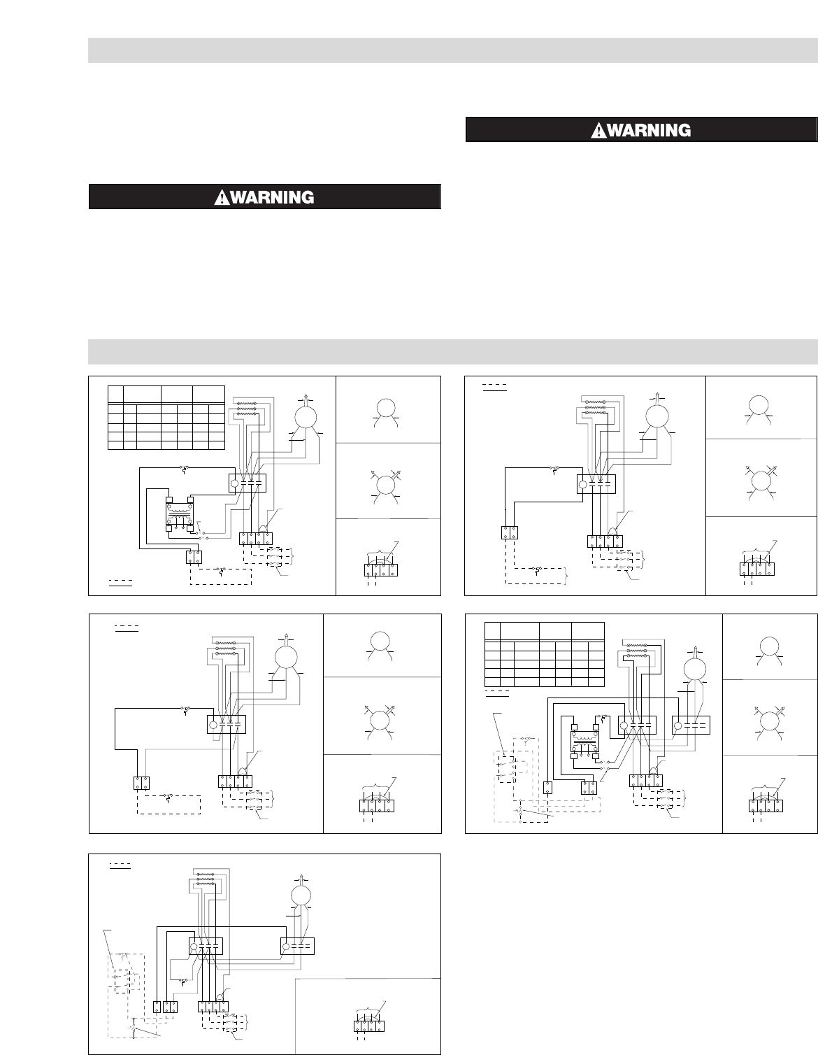
WIRING DIAGRAMS
VOLT
Transformer Color Code Index
PRI XFMR
LEAD CLRS
120V SEC.
LEAD CLRS
24V SEC.
LEAD CLRS
208
240
277
480
H1
BLK
BLK
BLK
BLK
X1
BLK
BLK
BLK
BLK
X2
WHT
WHT
WHT
WHT
X1
YEL
YEL
YEL
YEL
X2
BLU
BLU
BLU
BLU
H2
RED
ORG
BRN
BLK/RED
L1
L1
L2
C1
C1
X1
C2
TB2
Customer Wiring
Factory Wire
XFMR
Fusing
Optional
XFMR
L3
L2L3
T4
T1 T3
X2
H1 H2
Thermostat
(By Others)
Contactor
Cutout
Elements
3ø Jumper
Hook-Up
Fused Switch
(By Others)
3ø
Power
60 HZ
WHT
RED
TB1
YEL
M
BLU
BLK
208 - 240V Motor
Hook-Up
T1
T2
M
277V Motor
Hook-Up
BLK BLK
L1 L2 L3 T4
1ø Power
1ø Jumper
Hook-Up
TB1
To Contactor
WHT
RED
T1
T2
YEL
M
BLU
480V Motor
Hook-Up
BLK
T2
Figure 3
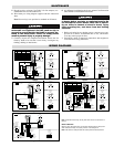
MAINTENANCE
5. Rough-in wiring to heater. See Table 2 for line amperes, rec-
ommended wire size and conduit size.
6. Wire heater per wiring diagram supplied with this instruction
sheet.
Note: Power relay(s) are provided as standard on all heaters.
Prior to operating the heater, verify that the fan hub
setscrews are tightened and the push-on clip is
secured to assure that the fan blade is securely fas-
tened to the motor shaft. Failure to comply could
result in personal injury or property damage.
7. Carefully inspect the completed installation. Rotate the fan
blade by hand to be sure that it turns freely. Investigate any
binding, rubbing or interference.
8. Air diffusers for deflecting the air are optional. See Instruction
Sheet PF449 for installation instructions.
ELECTRIC SHOCK HAZARD. Disconnect all power
to heater before servicing or replacing heaters. Do
not attempt to service heater while unit is operat-
ing as there is hazard of electric shock, injury
from operating fan, and burns from hot heating
elements.
1. Before activating for next heating season, vacuum or use com-
pressed air to remove accumulated dust or lint, which other-
wise may restrict proper air flow.
2. Periodically check all electrical connections and retighten to
avoid electrical wiring difficulties.
Note: For 208-240V motor wiring, red and yellow motor wires to be connected at T2
terminal.
MOTOR LUBRICATION
Motors in VUH-C-05 through VUH-C-10 have sleeve bearings which are factory lubri-
cated. Relubricate annually, if neccessary, with No. 10 non-detergent oil.
Note: All fan motors are totally enclosed and internally thermal overload protected.
L1
L1
L2
C1
C1
C2
TB2
Customer Wiring
Factory Wire
L3
L2
L3
T4
T1 T2 T3
Thermostat
(By Others)
Contactor
Cutout
Elements
3ø Jumper
Hook-Up
Fused Switch
(By Others)
3ø
Power
60 HZ
Control
Power
(By Others)
WHT
WHT
RED
RED
T1
T2
T1
TB1
T2
YEL
YEL
M
M
M
BLU
BLU
BLK
208 - 240V Motor
Hook-Up
277V Motor
Hook-Up
480V Motor
Hook-Up
BLK BLK
BLK
L1 L2 L3 T4
1ø Power
1ø Jumper
Hook-Up
TB1
To Contactor
Figure 4
L1 L2 L3 T4
L1
L1
L2
C1
C1
C2
TB2
Customer Wiring
Factory Wire
L3
L2
L3
T4
T1 T2 T3
Thermostat
(By Others)
Contactor
Cutout
Elements
3ø Jumper
Hook-Up
Fused Switch
(By Others)
3ø
Power
60 HZ
1ø Power
1ø Jumper
Hook-Up
WHT
WHT
RED
RED
T1
T2
T1
TB1
TB1
To Contactor
T2
YEL
YEL
M
M
M
BLU
BLU
BLK
208 - 240V Motor
Hook-Up
277V Motor
Hook-Up
480V Motor
Hook-Up
BLK BLK
BLK
Figure 5
VOLT
Transformer Color Code Index
PRI XFMR
LEAD CLRS
120V SEC.
LEAD CLRS
24V SEC.
LEAD CLRS
208
240
277
480
H1
BLK
BLK
BLK
BLK
X1
BLK
BLK
BLK
BLK
X2
WHT
WHT
WHT
WHT
X1
YEL
YEL
YEL
YEL
X2
BLU
BLU
BLU
BLU
H2
RED
ORG
BRN
BLK/RED
L1 L2 L3 T4
L1
L1
L2
C2
C4
C1
X1
C1
TB2
TB2
Customer Wiring
Factory Wire
XFMR
Fusing
Optional
XFMR
L3
L2 L3
T4
T1 T2
T3
X2
H1
Heat
Fan
H2
L1
C3
L2
L3
T1 T2 T3
Thermostat
(By Others)
2 PDT Switch
(By Others)
Optional Heat Recovery Switch
(By Others)
Contactor
Cutout
Elements
3ø Jumper
Hook-Up
Fused Switch
(By Others)
3ø
Power
60 HZ
1ø Power
1ø Jumper
Hook-Up
WHT
WHT
RED
RED
T1
T2
T1
TB1
TB1
To Contactor
T2
YEL
YEL
M
M
M
BLU
BLU
BLK
208 - 240V
Motor
Hook-Up
277V Motor
Hook-Up
480V Motor
Hook-Up
BLK BLK
BLK
Figure 6
L1 L2 L3 T4
L1
L1
L2
C2
C4
C1
C1
TB2
Customer Wiring
Factory Wire
L3
L2 L3
T4
T1 T2
T3
Heat
Fan
L1
C3
L2
L3
T1 T2 T3
Thermostat
(By Others)
2 PDT Switch
(By Others)
Optional Heat Recovery Switch
(By Others)
Contactor Contactor
Cutout
Elements
3ø Jumper
Hook-Up
Fused Switch
(By Others)
3ø
Power
60 HZ
1ø Power
1ø Jumper
Hook-Up
WHT
RED
TB1
TB1
To Contactor
YEL
M
BLU
BLK
208 - 240V
Motor
Hook-Up
Figure 7