


IMPORTANT
Failure to understand and follow these installation instructions
and the “WARNING” notes therein may result in serious per-
sonal injury from electrical shock, or from the heater falling due
to faulty installation.
FIRE/EXPLOSION HAZARD. This heater is not
intended for use in hazardous atmospheres where
flammable vapors, gases, liquids or other com-
bustible atmospheres are present as defined in
the National Electrical Code. Failure to comply can
result in personal injury or property damage.
ELECTRIC SHOCK HAZARD. Disconnect all power
before installing or servicing heater. Failure to do
so could result in personal injury or property dam-
age. Heater must be installed by a qualified per-
sonal in accordance with the National Electrical
Code, NFPA 70.
The heater must be mounted at least 7’ above the floor to prevent
accidental contact with the heating elements or fan blade which
could cause injury.
The ceiling structure, the brackets, hangers or chains used to sus-
pend the heater, and the anchoring provisions must be of sufficient
strength to support the combined weight of the heater installation
(48 pounds for VUH-C-05, 07, 10 plus the weight of the supports).
Prior to operating the heater verify that the fan hub setscrews are
tightened and the push-on clip is secured to assure that the fan
blade is securely fastened to the motor shaft.
On models connected to three-phase power, fan blade rotation
must be checked. If airflow is not downward, interchange any two
of the three customer power leads.
First stage of thermostat must be connected to terminals C1 and
C2 to insure proper operation of overheat protective devices.
INSTALLATION
ELECTRIC SHOCK HAZARD. Any installation
involving electric heaters must be performed by a
qualified person and must be effectively grounded
in accordance with the National Electrical Code to
eliminate shock hazard.
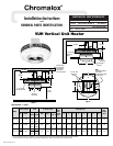
1. Heater should be positioned with the junction box facing away
from walls to provide easy access for servicing relay(s)
mounted within. See Figure 1.
Mount the heater for down discharge only. Failure
to comply may result in personal injury or property
damage.
2. It is important that the 12” minimum dimension shown in
Figure 1 be maintained to make it possible for a serviceman to
remove the fan motor, if necessary, without moving the heater
from its mounting.
The heater must be mounted at least
7’ above the floor to prevent accidental contact
with the heating elements or fan blade which
could cause personal injury.
The ceiling structure, the brackets, hangers or chains used to sus-
pend the heater and the anchoring provisions must be of sufficient
strength to support the total weight of the heater installation (48
pounds for VUH-C-05, 07, 10 plus the weight of the supports).
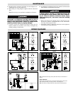
3. The heater to be mounted to the ceiling by attaching rigid
angle brackets, hangers, or chains to the four mounting holes
on the top of the heater case using four 5/8” bolts (by others).
See Figures 1 and 2.
Note: Brackets, hangers, or chains to support the heater are
supplied by the customer.
4. All wiring should be done in accordance with local codes and
the National Electrical Code by a qualified person.
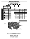
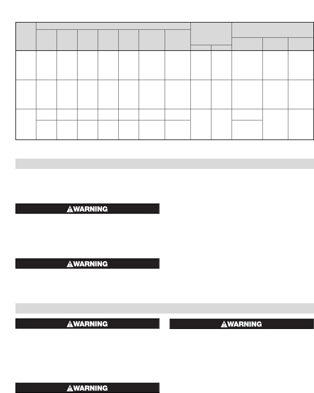
Power Supply Circuit
Contactor
Holding Coil
Motor
Model
Minimum Volt Ampheres
kW Volts Phase
Line Line
No.
Conduit (Note 3)Amps Wire Size
Circuits
Size †(Note 1) (Note 2)
Inrush Sealed
Volts H.P. Phase
208 1 25 8 1 3/4” 208/240
208 3 15 12 1 1/2” 280/240
240 1 22 10 1 1/2” 208/240
VUH-C-05 5
240 3 13 12 1 1/2”
60 9
208/240
1/25 1
277 1 19 10 1 1/2” 277
480 3 7 14 1 1/2” 480
208 1 37 6 1 3/4” 208/240
208 3 22 10 1 1/2” 208/240
240 1 32 8 1 3/4” 208/240
VUH-C-07 7.5
240 3 19 10 1 1/2”
60 9
208/240
1/25 1
277 1 28 8 1 3/4” 277
480 3 10 14 1 1/2” 480
9.8
208 1 48 6 1 3/4” 208/240
208 3 29 8 1 3/4” 208/240
240 1 43 6 1 3/4” 208/240
VUH-C-10 10
240 3 25 8 1 3/4”
60 9
208/240
1/25 1
277 1 37 6 1 3/4” 277
480 3 13 12 1 1/2” 480
Table 2 - Electrical Data
Notes:
1. Includes Fan Motor Amps.
2. Use 75˚C Wire - Copper Conductors only.
3. Standard units have one contactor. Units with separate fan
motor control use two contactors.
† Conduit knockout location - top of Junction Box.