


INSTALLATION
6. Heater must not be operated in sludge.
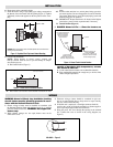
7. Install the heater using a high quality pipe sealing compound on
the threads. Screw the heater into the opening (Figure 2). Tighten
sufficiently with wrench applied on the hex portion of the screw-
plug.
8. Closed Tank Installation
NOTE: When heating in closed vessels, controls and
back-up controls must be used to prevent buildup of temper-
ature and/or pressure.
A. Horizontal Position (Figure 3)
A1. Place heater at an elevation so that natural circulation can take
place.
A2. Position outlet and inlet in a vertical plane, facing upward to
prevent air pockets. Be sure all trapped air is removed from the
closed tank. Bleed the air out of the liquid piping system and
heater housing prior to operation.
A3. IMPORTANT: Heater should never be located at the highest
point in the system. Provide expansion tank, if necessary.
B. Vertical Position (Figure 4)
9. DANGER: Hazard of Fire — Since the heaters are
capable of developing high temperatures, extreme
care should be taken to:
A. Avoid contact between heaters and combustible materials.
B. Keep combustible materials far enough away to be free of the
effects of high temperatures.
Locate Drain Pipe
at Bottom of Heater.
Sediment Deposits may be
Removed Through Drain Pipe
Maximum Sediment Level.
Install Heater Above
This Level But as Near to it as
Possible for Maximum Heated
Solution Storage Capacity
Suitable
Wiring
Drip Loop Recommended
to Minimize Passage of
Moisture Along Wiring
Into Terminal Wiring
and Connections
Outlet
Inlet
Figure 4 - Closed Tank in Vertical Position
Heater
Outlet
Inlet
Note: In a Forced Circulation System,
Use Pump In Inlet Side
Figure 3 - Closed Tank in Horizontal Position
WIRING
WARNING: Hazard of Shock. Any installation involving
electric heaters must be effectively grounded in accor-
dance with the National Electrical Code.
1. Electric wiring to heater must be installed in accordance with
the National Electrical Code and with local codes by a qualified
person as defined in the NEC. WARNING: Use copper con-
ductors only.
2. When element wattages are not equal, heaters must not be
connected in series.
3. Electrical wiring to heater should be contained in rigid con-
duit or in sealed flexible hose to keep corrosive vapors and liq-
uids out of the terminal housing.
4. If flexible cord is employed, a watertight connector should be
used for entry of the cord into the terminal box. Outdoor applica-
tions require liquid-tight conduit and connectors.
5. Bring the power line wires through the opening in the terminal
box. Connect line wires as shown in the wiring diagram (see
Figure 5).
WARNING: Care must be taken to insure the heated portion does not extend into the
coupling area (see Dimensions).
Approx. 6” Cold
Figure 2 - Exploded View Pipe Insert Heater Mounting
2”
L-1
L-2
240-480V — Figure 5