© 2010 Chromalox, Inc.
Type MTO-LT
Pipe Insert Immersion Heater
GENERAL
WARNING: Calculate and allow for thermal expansion.
Pipe insert will expand upon heating. The rear end of the
pipe insert must remain free from the tank wall. Heating
elements will also expand upon heating and must not
extend to the end of the pipe insert.
Chromalox type MTO-LT screwplug immersion heater is designed
for insertion into a 2” or larger pipe.
WARNING: It is the responsibility of the purchaser of the heater to make
the ultimate choice of pipe material based upon his knowledge of the
chemical composition of the corrosive solution, character of the material
entering the solution and controls which he maintains on the process.
Chromalox cannot warrant any electric immersion heater against failure,
if such failure is the result of corrosion due to improper material selec-
tion by the user.
1. Heater Construction Characteristics:
A. High quality resistance wire held in place by compacted
Magnesium Oxide Refractory enclosed in an Incoloy® sheath.
B. Low to High Watt densities.
C. Explosion Resistant/Liquid-Tight E-2 terminal enclosures
are standard.
WARNING: Users should install adequate controls and
safety devices with their electric heating equipment.
Where the consequences of failure may be severe, back-
up controls are essential. Although the safety of the
installation is the responsibility of the user, Chromalox
will assist in identifying equipment options.
INSTALLATION
WARNING: Hazard of Shock. Disconnect all power
before installing heater.
1. Before installing, check your type MTO-LT pipe insert heater
for any damage that may have occurred during shipment.
2. Check to insure that the line voltage is the same as that stamped
on the nameplate.
3. Do not bend the heating elements. If bending is necessary,
consult factory.
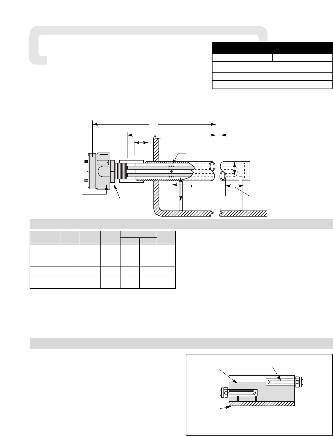
4. IMPORTANT: Mount heater in the tank so that the liquid level
will always be above the effective heated portion of the heater (see
Figure 1). If the heater is not properly submerged, it may overheat
and damage the heating elements and create a possible fire hazard
due to excessive sheath temperatures.
5. Where work will pass over or near equipment, additional protec-
tion such as a metal guard may be needed.
Note: Locate Heater as low as possible for maximum liquid storage capacity. Heat
does not move downward.
Figure 1 - Open Tank Installation
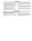
Dim. (In.) Pipe
Model kW Volts Phase A B Thd.
MTO-241LT 4 240 1 127 120 2
MTO-241LT 4 480 1 127 120 2
MTO-251LT 5 240 1 163 156 2
MTO-251LT 5 480 1 163 156 2
MTO-275LT 7.5 240 1 211 204 2
MTO-275LT 7.5 480 1 211 204 2
MTO-212LT 11.5 480 1 319 312 2
MTO-213LT 13 480 1 367 360 2
Expected Low
Level of Liquid
This Portion of Heater Above Liquid Level and
Exposed to Air Will Lead to Premature Burnout of Element
Expected Maximum
Sediment Level
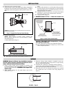
Type E2
Moisture-Tight
Explosion-Resistant
Enclosure
A
B
Spacer
Expansion Gap
Pipe, Support &
Tank (by others)
Expansion Gap
2-1/16”
I.D. Min.
2-3/8”
Max.
3/4” Pipe Outlet
RIGHT
WRONG