


ELECTRIC SHOCK HAZARD. Disconnect all power
before installing or servicing heater. Failure to do
so could result in personal injury or property dam-
age. Heater must be installed by a qualified person
in accordance with the National Electrical Code,
NFPA 70.
ELECTRIC SHOCK HAZARD. Any installation involv-
ing electric heaters must be performed by a quali-
fied person and must be effectively grounded in
accordance with the National Electrical Code to
eliminate shock hazard.
1. The power supply voltage should be the voltage as specified on the
heater nameplate located on the heater housing.
2. Wiring should be run in flexible or rigid metal conduit and must be
installed in accordance with the requirements of the National
Electrical Code and such other local requirements as may be
applicable. Note: High temperatures will oxidize copper. Do not
use copper wire in connecting this heater. Nickel-plated copper
wire, insulated in accordance with requirements for temperature
and voltage is recommended.
3. A sufficient length of this wire (not less than 12”) should be used
to extend from each heater terminal into a connection box location
where the temperature does not exceed 300˚F.
4. ELECTRICAL CONNECTIONS —
A. End Elements
Electrical connection to the heater end elements is made
through the 7/8” dia. opening in the end of the terminal cover
of the element assembly. A 1/2” flexible conduit connector is
provided with each element assembly for this purpose.
B. Center Elements
Electrical connection to the heater center element is made
through the 7/8” dia. opening in the 4” octagon conduit box for
the element assembly. A 1/2” flexible conduit connector is pro-
vided with each element assembly for this purpose.
5. ACCESS TO TERMINALS
A. End Elements
Access to the end element terminals is obtained by removing
the mounting bolt, nut and spacer (see Figure 9, items 9, 16 and
18) and sliding the terminal end of the element assembly out of
the housing.
B. Center Elements
Access to the center mounted element terminals is obtained by
removing the terminal box cover.
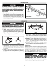
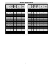
6. END ELEMENT TERMINAL ASSEMBLY
Assemble end terminal, screw and wire as shown in Figure 5. Hold
terminal with pliers and tighten the terminal screw securely with a
screwdriver.
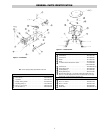
7. CENTER ELEMENT TERMINAL ASSEMBLY
Assemble center terminal, washers, nut and wire as shown in
Figure 6. Hold terminal with pliers and tighten the terminal nut
securely with a wrench.
CAUTION: Terminal clip is spot-welded to element terminal pin
and over-tightening terminal screw may break the weld or shear
off terminal pin. However, either the screw or nut should be suffi-
ciently tightened to eliminate arcing.
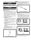
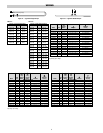
8. SERIES CONNECTION of Radiant Heaters of equal volt and
watt rating is permitted in all line voltages up to 600 volts. In mak-
ing such series connections it is necessary to observe the “right”
(series-parallel) connection rather than the “wrong” (parallel-
series) connection both shown in Figure 7. If heaters are connect-
ed according to the “wrong” illustration, failure of any heater will
cause progressive failure of other heaters still operating.
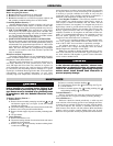
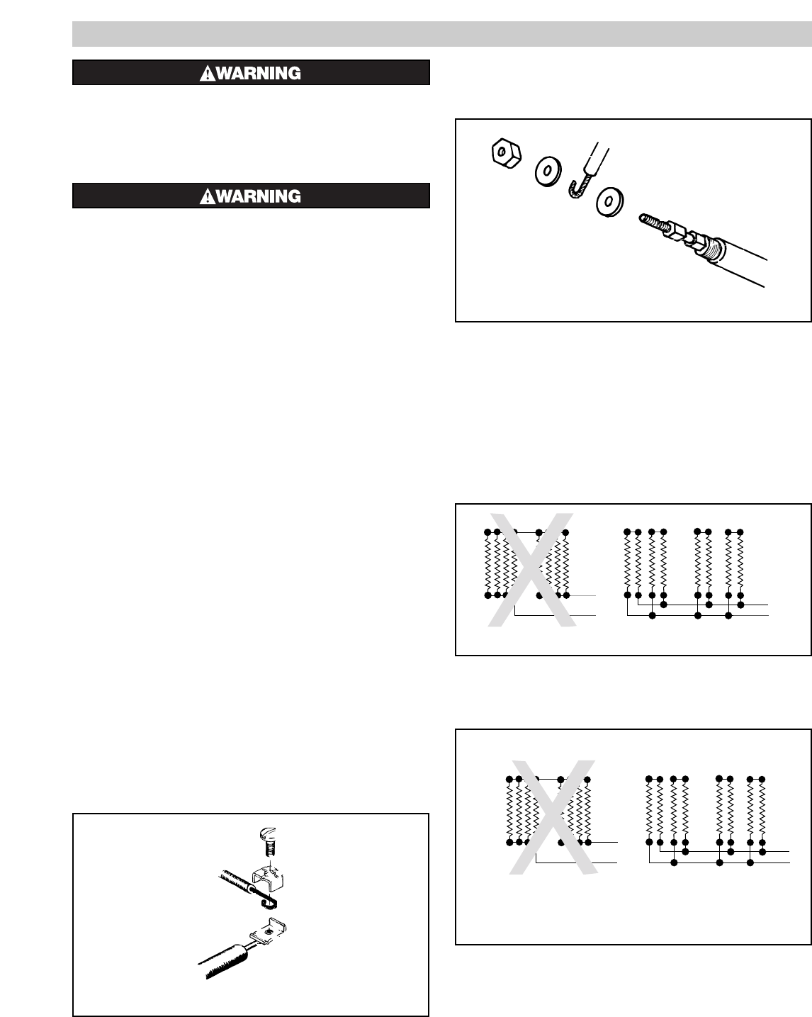
9. DELTA CONNECTIONS — When heaters occur in multiples of
three, they may be connected to, and balanced across, three-phase
lines. The most commonly used connection is the delta connection
illustrated in Figure 8.
Three phase Delta connections to minimize inductive effect in
conduits are made per this diagram. The rule: run all 3 three-phase
conductors in the same conduit as far as possible. For single-phase,
run only two conductors and follow the same rule.
3
WIRING
Wrong
Right
L1
L2
L2
L1
Radiant
Heaters
Wrong
Right
L1
L2
L2
L1
Radiant
Heaters
Figure 5 — End Element Terminal Assembly
Figure 7
Figure 8
Figure 6 — Center Element Terminal Assembly