


2
INSTALLATION
MOUNTING
The system designer is responsible for the safety
of this equipment and should install adequate
back-up controls and safety devices with their
electric heating equipment. Where the conse-
quences of failure could result in personal injury or
property damage, back-up controls are essential.
Before Installing
1. Open carton and remove heater at the place of installation.
Mounting clamps are in parts bag in carton.
2. Check nameplate volt and watt rating against your power supply
voltage and heating requirements of your installation. This name-
plate of the complete assembly is located on the back of the heater
housing. Note: Single element heaters have one nameplate. Three
element heaters have four nameplates (one for each element and
one for the complete assembly).
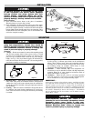
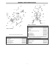
Housing
1 / "
7
8
Mounting Clamp
Assembly
Terminal
Cover
Terminal
Blocks
Polished Aluminum
Reflector
Element
Figure 1 — Heater Parts
and Dimensions
FIRE HAZARD. Since heaters are capable of devel-
oping high temperatures, extreme care should be
taken to maintain adequate spacing between heater
and combustible materials. Failure to comply can
result in personal injury or property damage.
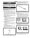
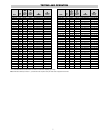
Mounting
1. Clamps — Heaters are mounted by means of the mounting clamp
and 3/8” bolt assembly which is used as shown in Fig. 2. Clamp
assembly may be attached to heater by sliding over end or by snap-
ping over top of extruded frame section at any point along its
length. (see Fig. 3) For proper heater support, the maximum dis-
tance between clamps must not exceed 48”. On extra-long heaters,
more than two clamps are furnished.
2. Mounting Holes — When heaters are mounted adjacent to each
other in the same plane, the minimum distance will depend on
whether the wiring to the center element enters the terminal box
through the connector furnished or through a right angle connector
(not furnished).
3. Framing — Where an extensive installation is being made, the use
of continuous slot metal framing manufactured by several con-
cerns will be of assistance in saving time and money. The framing
is reusable.
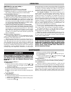
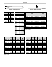
4. Reflector Spacer Sheets — Where heaters are not mounted side
by side (see Fig. 4), reflector spacer sheets can be used between
heaters. These reflector spacer sheets and companion reflectors
consisting of an extruded aluminum housing with reflector sheet
and mounting clamps are available. Check factory or local
Chromalox Sales and Application Engineers.
5. Insulation — Where unusually high work temperatures are
encountered, it may be desirable to insulate with high temperature
insulation. Note: An air space should be left between backs of
heaters and insulation. (see Figure 4)
6. Ventilation — Where solvents, water, etc. are being evaporated
from work in process, it is necessary to provide substantial quanti-
ties of ventilation air to carry away the resulting vapors.
IMPORTANT –
In the case of solvents of an explosive nature, ventilation air must
be in sufficient volume to dilute the solvent vapor so that explosive
mixtures cannot occur. In order to comply with the standards of
safety required by the insurance companies, ventilation protection
and other facilities must be in accordance with NFPA Bulletin No.
86, entitled “Standard for Ovens and Furnaces”. This Bulletin
may be obtained from the Association at 470 Atlantic Avenue,
Boston Mass., 02110
FIRE/EXPLOSION HAZARD. This heater is not
intended for use in hazardous atmospheres where
flammable vapors, gases, liquids or other com-
bustible atmospheres are present as defined in the
National Electrical Code. Failure to comply can
result in personal injury or property damage.
2 / "
15
16
2 / "
3
8
3 / "
11
16
Figure 2 Figure 3
Mounting Frame
Reflector
Spacer Sheet
Insulation
Figure 4