


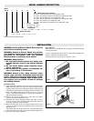
1. Unpack the heater from the carton and remove the front panel.
Note: The front panel screws are recessed at the bottom of the
front panel at each end of the heater.
2. Remove the desired terminal box covers and wire supply
knockouts from the terminal box area.
3. Use trim frame as a template to drill holes into the top, bottom
and sides of the heater using a 1/8” diameter drill bit.
4. Secure the trim frame using the #8 screws provided with the
trim kit.
TIP: The bottom trim may be omitted if the heater is to be
installed at floor level.
5. Prepare the wall recess opening to accept the heater.
TIP: Leave approximately 1/2” clearance to insert the heater
cabinet.
6. Secure the back plate into the recess opening using suitable
fasteners (Provided by customer).
7. Proceed to the wiring instructions.
INSTALLATION (Recessed Wall)
WIRING
Note: All wiring should be done in accordance with local codes
and the National Electrical Code by a qualified person.
1. Run branch circuit wiring of proper voltage and wire size to the
location of the terminal box of the heater.
TIP: Supply wire entry is commonly made into one heater.
Through wiring (factory furnished) can be used for connection
to adjacent heaters.
Recommended minimum supply wire sizes are listed in the table
below:
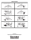
2. Wire all heaters and controls in accordance with the appropri-
ate wiring diagram.
TIP: Sample wiring diagrams are provided on page 4.
3. Wrap the supply ground wire to the green painted ground
screw and tighten.
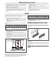
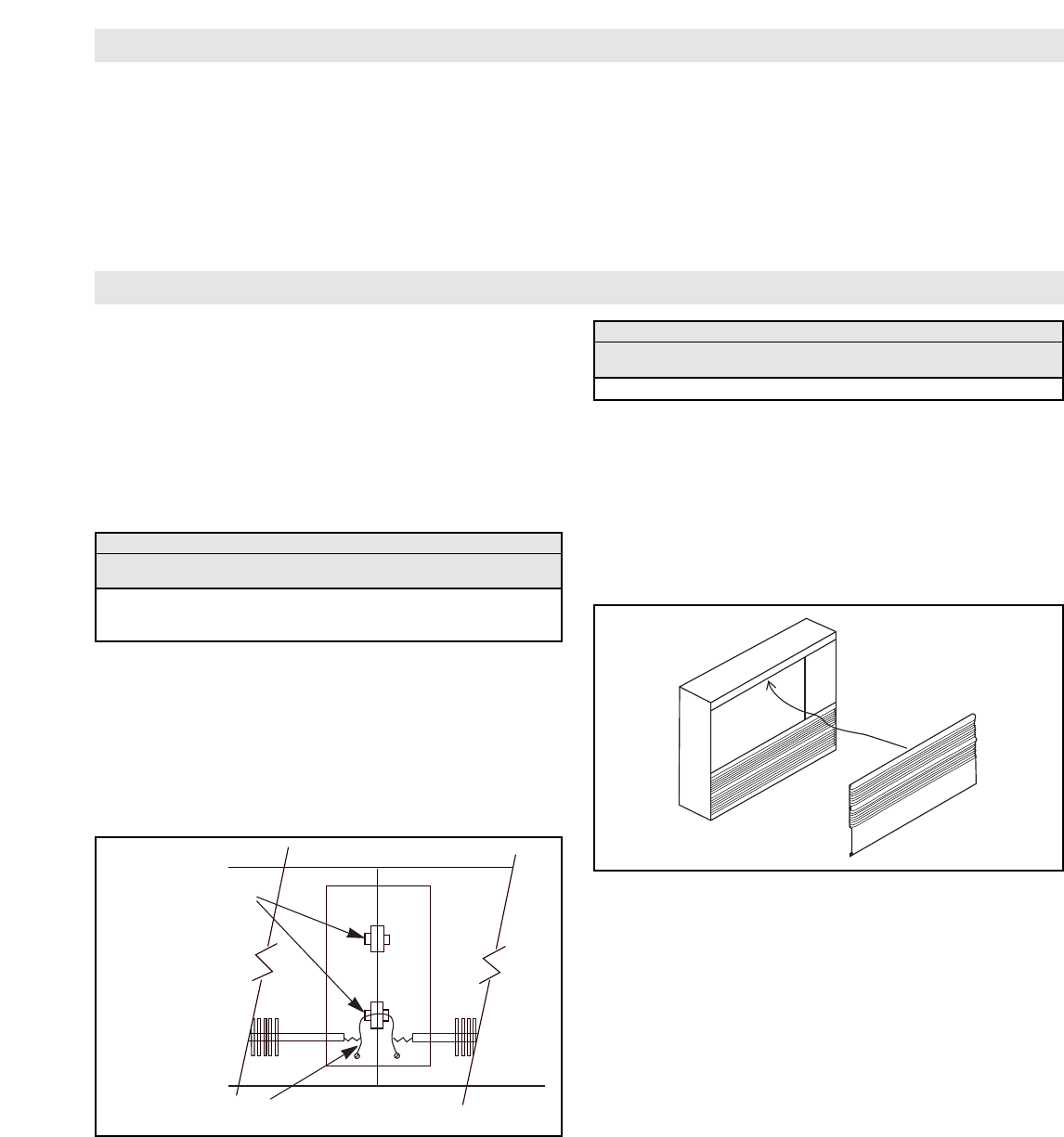
Note: When heaters are mounted end to end, remove the fin-
ishing end plate, install a chase nipple and locknut in the ter-
minal box to insure grounding continuity, and to protect the
wiring. (Figure 4)
Where heaters are spaced apart, remove the finishing plate and use
rigid conduit (provided by customer) for through wiring and
ground continuity. Do not exceed the allowable number of con-
ductors allowed by the National Electrical Code.
4. Do a final and complete check of all wiring then replace the
terminal box covers.
5. The front panel may now be installed.
WARNING: To prevent the risk of fire, do not oper-
ate the heater without the front cover in place.
Insert the top of the front panel into the top flange of the heater.
Push the bottom flange of the front panel into place and secure
with screws.
Maintenance
The CAF-20 series heaters contain no moving parts. Occasional
vacuum cleaning of the cabinet interior is the only maintenance
required.
WARNING: Before removing the front cover for
cleaning, make certain supply power is discon-
nected.
Maximum Watts Per Circuit Using 75°C. Wire
Rough In
Wire Size120V 208V 240V 277V 347V 480V 600V
14 1440 2496 2880 3324 4164 5760 7200
Copper 12 1920 3328 3840 4432 5552 7680 9600
Wire 10 2880 4992 5760 6648 8328 11520 14400
Terminal Box Volumes (Cubic Inches)
Heater Style Left Hand Box Right Hand Box
4” Wide 5” Wide
CAF-20 379.75 474.75
Chase Nipples
Installation Between
Heaters Butted Together
Ground Wire Running
Through Chase Nipple
Figure 4
Figure 5