


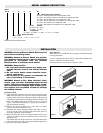
MODEL NUMBER DESCRIPTION
WARNING: Hazard of Electric Shock. Disconnect all
power before installing heater.
WARNING: Hazard of Electric Shock. Any installa-
tion involving electric heaters must be effectively
grounded in accordance with the National
Electrical Code to eliminate shock hazard.
WARNING: Hazard of Fire.
1. Do not install heaters against any highly com-
bustible surfaces such as low density cellulose
fibre.
2. Do not locate heater below electrical conve-
nience receptacles.
3. Do not store or use gasoline or flammable liq-
uids in the vicinity of the heaters.
WARNING: Hazard of Fire. Keep electrical cords,
drapes, rugs and other furnishings away from the
heater. The normal operating temperatures of cab-
inet convectors are relatively high. Proper opera-
tion requires free circulation of room air through
the heating element.
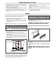
Installation Wall
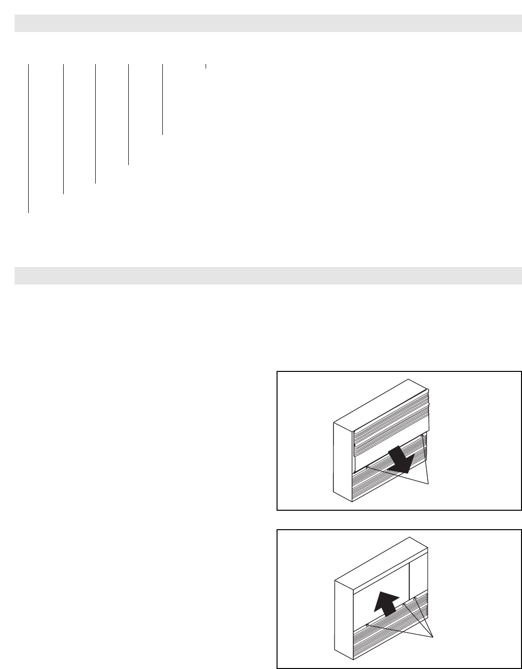
1. Unpack the heater from the carton and remove the front panel.
Note: The front panel screws are recessed at the bottom of the
top front panel at each end of the heater. (Figure 2) Remove top
front panel by pulling down to disengage from top of heater. To
remove the bottom front panel, remove screws as shown in
Figure 3. Pull bottom front panel by pulling upward to disen-
gage from bottom of heater.
2. Remove the desired terminal box covers and wire supply
knockouts from the terminal box area.
3. Determine the correct mounting height, and scribe or snap a
level line on the wall to maintain each heater back plate in a
horizontal alignment, when mounting.
4. Mount the back plate to the wall using suitable fasteners (pro-
vided by customer) using the scribed line on the wall to keep
the heater level.
TIP: Should the wall surface be uneven, secure the heater back
panel to the high spots. This will avoid a distorted appearance.
5. Proceed to the wiring instructions.
Recessed Wall
Note: The use of a ALTB Trim kit is strongly recommended when
recessing the heater.
A recess opening dimension of 20-1/2” high and the length of the
heater is required to install this heater.
The heater may be recessed up to a depth of 5-5/8”.
INSTALLATION
Top Panel
Screws
CAF-20 2 20 21 01 A9
Code Control Options (Factory Installed)
A9 = Built-in DP tamperproof hydraulic thermostat 208 - 480V
A3 = Built-in 3P tamperproof hydraulic thermostat for 3P voltages 208 - 480V
A4 = Built-in 24V low voltage relay for 1P voltages 208 - 480V
A5 = Built-in 24V low voltage relay and transformer for 1P voltages 208 - 480V
A6 = Built-in 24V contactor for 3P voltages 208 - 480V
A7 = Built-in 24V contactor and transformer for 3P voltages 208 - 480V
Painted Anodized
68 = Almond 07 = Bronze
02 = White 10 = Clear
Code Voltage/Phase
21 = 208/1 23 = 208/3 31 = 240/1 41 = 277/1 73 = 480/3
Code Wattage (See Table)
Code Length
2 = 2 ft. 3 = 3 ft. 4 = 4 ft. 5 = 5 ft. 6 = 6 ft.
Type
Architectural Cabinet Convection Heater
TABLE 2
Bottom
Panel
Screws
Figure 2
Figure 3