


6. In high ambient temperature operations, least corrosive action
and least oxidation to the terminals will occur if the heaters are
mounted with the terminals in the coolest possible ambient,
usually on the bottom or side of the duct.
A. Minimum duct size is “A” or “L” dimension +3/8” and “B”
dimension +1-5/8”.
HAZARD OF FIRE. Since these heaters are capable of
developing high temperatures, extreme care should
be taken to:
A. Avoid installing heaters in an atmosphere containing com-
bustible gases and vapors.
B. Avoid contact between heater and combustible material.
C. Keep combustible materials far enough away to be free of
the effects of high temperatures.
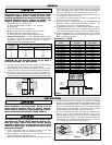
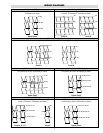
INSTALLATION (cont’d.)
Duct
Air
Air
Temperature Control Instructions
1. A Chromalox thermal cutout or thermostat is recommended for
overheat protection and control of heater and process. Consult
local Chromalox representative.
2. In general, place thermostat sensing element close to the heat-
ing elements, near top of duct, at right angles to the direction of
air flow, and on the downstream side of the heater. Thermostat,
provided with a manual reset button, is separately mounted.
3. For heater protection, the indicated maximum temperature of
the control unit should be 50°F less than the actual maximum
air temperature that will be permitted, to allow for overshoot.
4. Single circuit heater elements may be wired into two circuits to
allow for partial heating and control. It is important to have
thermal control wired into all electric power circuits, so that all
elements may be protected from overheat.
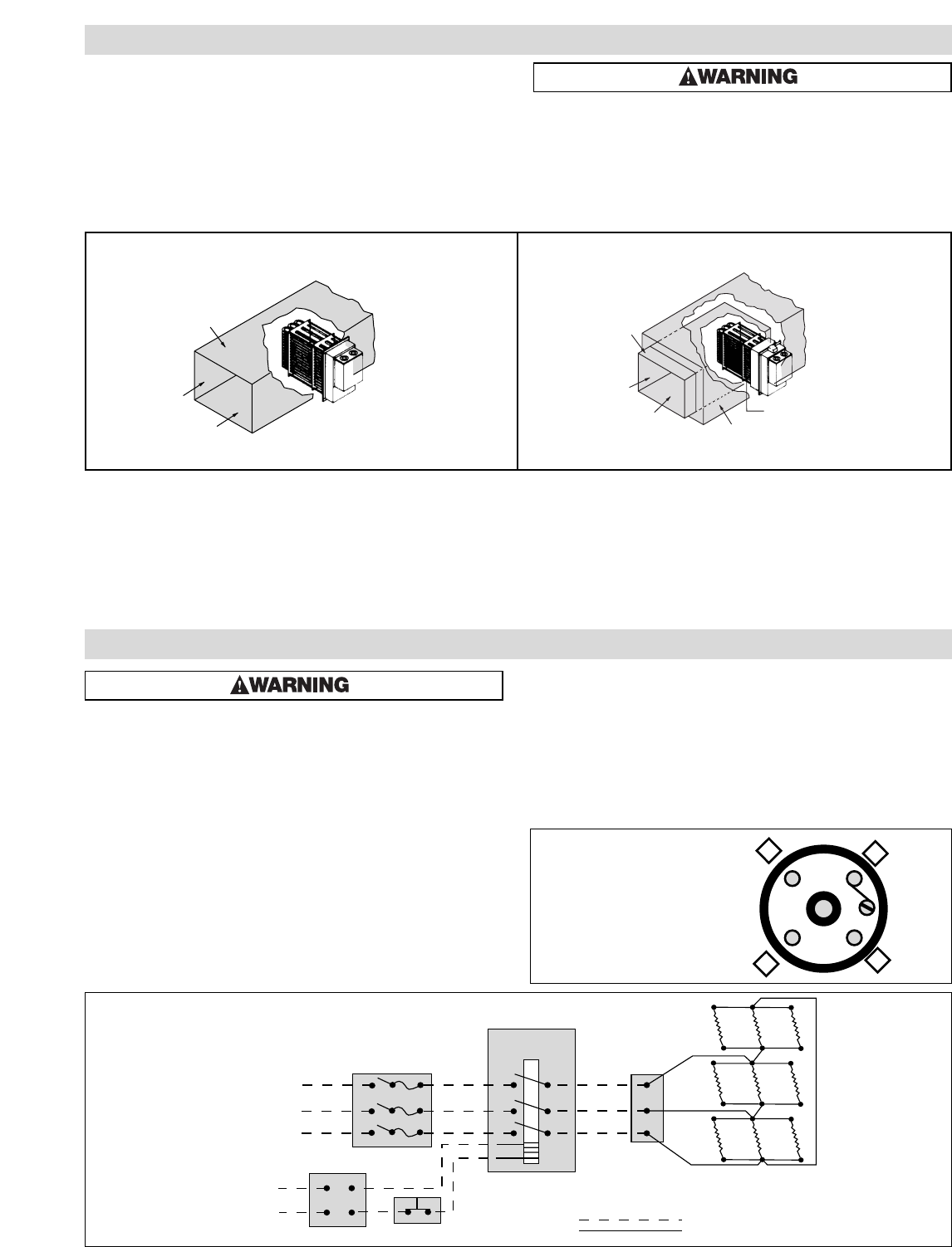
Figure 6 Figure 7
ELECTRIC SHOCK HAZARD. Any installation involv-
ing electric heaters must be performed by a quali-
fied person and must be effectively grounded in
accordance with the National Electrical Code to
eliminate shock hazard.
1. All wiring should be done in accordance with National Electrical
Code and with local codes by a qualified person.
2. Connect air heaters to same line voltage, phase, and frequency
as on heater nameplate.
3. Teflon insulated nickel plated copper wire or bus bar is recom-
mended for power connections to heater terminals and for
wiring runs in heated zones. When ambient temperature in
heated zone exceeds that for which insulated wire is recom-
mended use bare nickel-plated copper with porcelain beads,
tubing or bus bar. Consult local Chromalox representative.
4. Users should install adequate back-up controls and safety
devices with their electric heating equipment. Selection of con-
trols, thermostat, SCR units, contactors and etc. depends on the
degree of accuracy required, reliability, electrical rating of
heater and economic considerations.
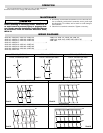
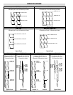
5. Below is an example of a standard ADH-015, 480V 3 Ø 15 kW,
wired with recommended back-up controls. (Figure 8)
6.
Individual terminal blocks with 1/4-20 threaded stud type terminals
are provided for each circuit to permit quick positive attachment of
circuit wiring conductors (one terminal block per circuit). (Figure 9)
WIRING
Magnetic
Contactor
Terminal
Block
Fused
Switch
Control Switch
Thermostat
Control
Voltage
120 or 240V
L1
L2
L3
L1
L2
L3
ADH-015
Customer Supplied Wiring
Factory Supplied Wiring
L1
L3
L2
G
✸
X Circuit label indicated here.
Terminal block
(303-027852-001)
Figure 8
Figure 9
ADH-015, 15 kW 480V 3ø, 1 Circuit
(9) - 480V, 1667 Watt Elements
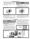
3
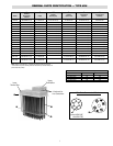
Duct
Air
Air
Insulation
(3" max.)
Standoff Colla
r
ADH Low temperature duct heaters — can be fastened directly to the sheet metal duct
work with bolts or sheet metal screws.
ADHT High temperature duct heaters — are generally mounted on field fabricated stand
off supports from the ductwork to position the heater such that the 3” insulation housing
is in the same plane as the duct insulation.