


ELECTRIC SHOCK HAZARD. Disconnect all power
before installing or servicing heater. Failure to do so
could result in personal injury or property damage.
Heater must be installed by a qualified person in accor-
dance with the National Electrical Code, NFPA 70.
The system designer is responsible for the safety of this
equipment and should install adequate back-up con-
trols and safety devices with their electric heating
equipment. Where the consequences of failure could
result in personal injury or property damage, back-up
controls are essential.
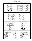
1. Locate and position heater in duct in accordance with both
process requirements and recommendations given.
2. Refer to Figures 1 and 2, layout “D” and “M” dimensions on
duct mounting face established in step 1.
3. With tools suitable for sheet metal work, cut layout opening in duct.
4. In general, heaters less than 35 pounds in weight may be mounted
directly in opening without additional duct reinforcement if duct
installation and condition permits. To fasten heater to duct wall use
#14 pan or round head self-tapping screws. The flange mounting
gasket supplied with the heater is recommended for insertion
between heater flange and duct to minimize air leakage.
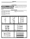
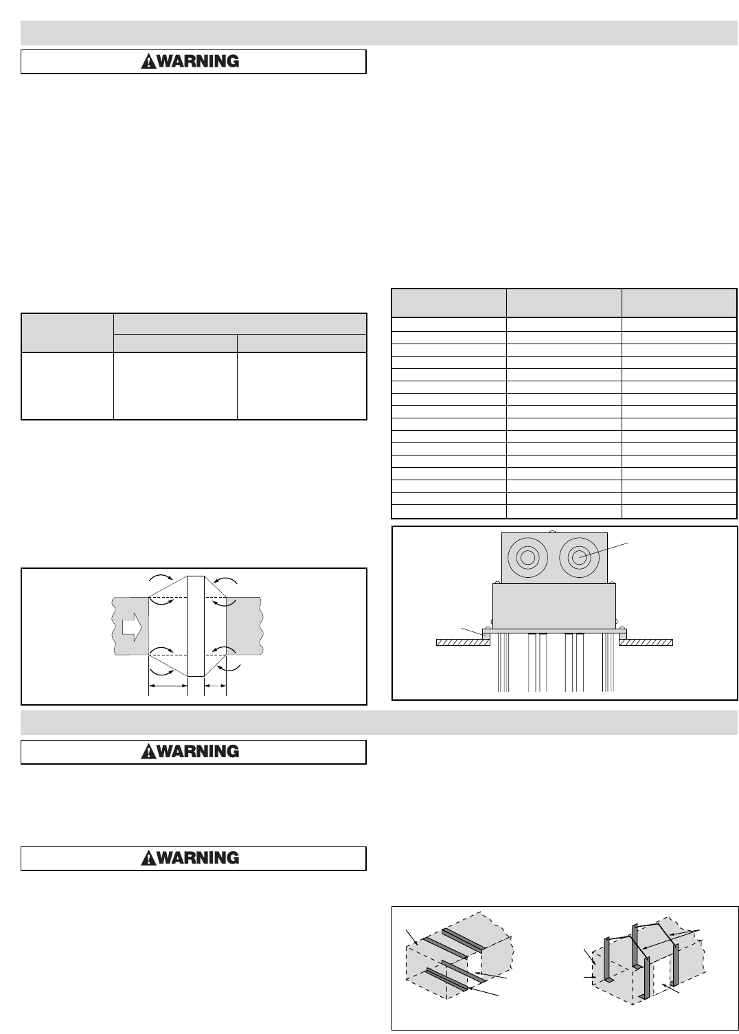
5. For heater weights greater than 35 pounds (see Specifications
Table A, page 1) due consideration should be given to; (a)
mechanically strengthening duct work with, for example, angle
irons or chains (see Figure 5), and (b) heat insulating duct line
in immediate area of heater location to prevent excessive heat
loss. Consult your local sheet metal contractor.
FIRE/EXPLOSION HAZARD. This heater is not
intended for use in hazardous atmospheres where
flammable vapors, gases, liquids or other com-
bustible atmospheres are present as defined in the
National Electrical Code. Failure to comply can
result in personal injury or property damage.
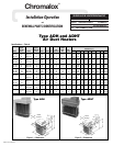
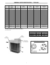
1. Heater construction characteristics —
A. Alloy sheathed tubular elements, .475” diameter
B. Steel flange
C. Stainless steel support construction
D. High temperature alloy terminals and connections
E. Replaceable individual heating elements
F. Wiring terminals located outside the heated zone
2. Maximum Temperatures — Types ADH and ADHT process
air heaters can generally be used at the following maximum
temperatures shown, provided the minimum air velocity is
maintained uniformly through the heater.
CAUTION: Do not energize heater in air with a
velocity less than 1 Ft. Per Second.
3. The heater may be bolted to the duct with the terminal housing
and flange at the top, at either side or at the bottom.
4. Several heaters may be mounted in tandem so long as proper
controls are used to limit the maximum temperature attained.
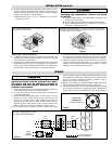
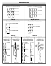
5. Installation with duct transitions in some air distribution sys-
tems, the duct heater may be considerably larger than the duct-
work and the duct area must be increased by a sheet metal tran-
sition. The slope of the transformation piece on the upstream
side of the equipment is limited to 30° as indicated in Figure 3.
On the leaving side, the slope should not be more than 45°.
6. Use moisture proof terminal cover in atmospheres bearing cor-
rosive fumes or excessive moisture.
7. Use explosion resistant heaters in explosive atmospheres and
reduce current rating to elements.
8. Gas tight design — Achieved by the use of threaded fittings
with fiber washers to attach heating elements to flange — pre
vents leakage of ducted air into terminal housing.
9. Overtemperature protection — Thermocouple fastened to the ele-
ment sheath surface and wired to a terminal block can be provid-
ed for accurate overheat protection (standard on ADHT models).
10. Flange mounting gasket — Packed separately with each duct
heater to minimize air leakage between the flange and air duct.
Refer to Table B and Figure 4.
GENERAL
Max. Outlet Air Temp. (˚F)
Air Velocity
(Ft./Sec.) ADH ADHT
4 800 1050
9 800 1100
16 800 1150
25 800 1200
36 800 1200
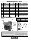
Flange Gasket Used On
Part No. Flange Size ADH and ADHT
168-055429-001 11-1/8 x 5-5/8 5 kW
168-055429-002 11-1/8 x 7-5/8 10 kW
168-055429-003 11-1/8 x 9-5/8 15 kW
168-055429-004 11-1/8 x 11-5/8 20 kW
168-055429-005 11-1/8 x 13-5/8 25 kW
168-055429-006 11-1/8 x 15-5/8 30 kW
168-055429-007 11-1/8 x 17-5/8 35 kW
168-055429-008 11-1/8 x 19-5/8 40 kW
168-055429-009 11-1/8 x 21-5/8 45 kW
168-055429-010 11-1/8 x 23-5/8 50 kW
168-055429-011 11-1/8 x 27-5/8 60, 120 kW
168-055429-013 11-1/8 x 35-5/8 80, 144, 160 kW
168-055429-014 11-1/8 x 39-5/8 90, 162, 180 kW
168-055429-015 11-1/8 x 43-5/8 100 kW
168-055429-017 20 x 27-5/8 216, 240 kW
168-055429-018 20 x 33-5/8 270, 300 kW
Specifications — Table B
Flange
Mounting
Gasket
Duct Wall
2-1/2" x 1-1/4" x 3/4"
Knockouts
45˚
45˚
Max
30"
Max
30˚
Duct Heater
Air
Flow
4 Ft. Min.
4 Ft. Min.
Figure 3
Figure 4
INSTALLATION
2
Heater
Opening
Angle Iron
Duct
Duct
Metal
Strapping
Heater Opening
Chains
Figure 5