


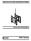
PDC Series Installation Instructions
6
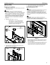
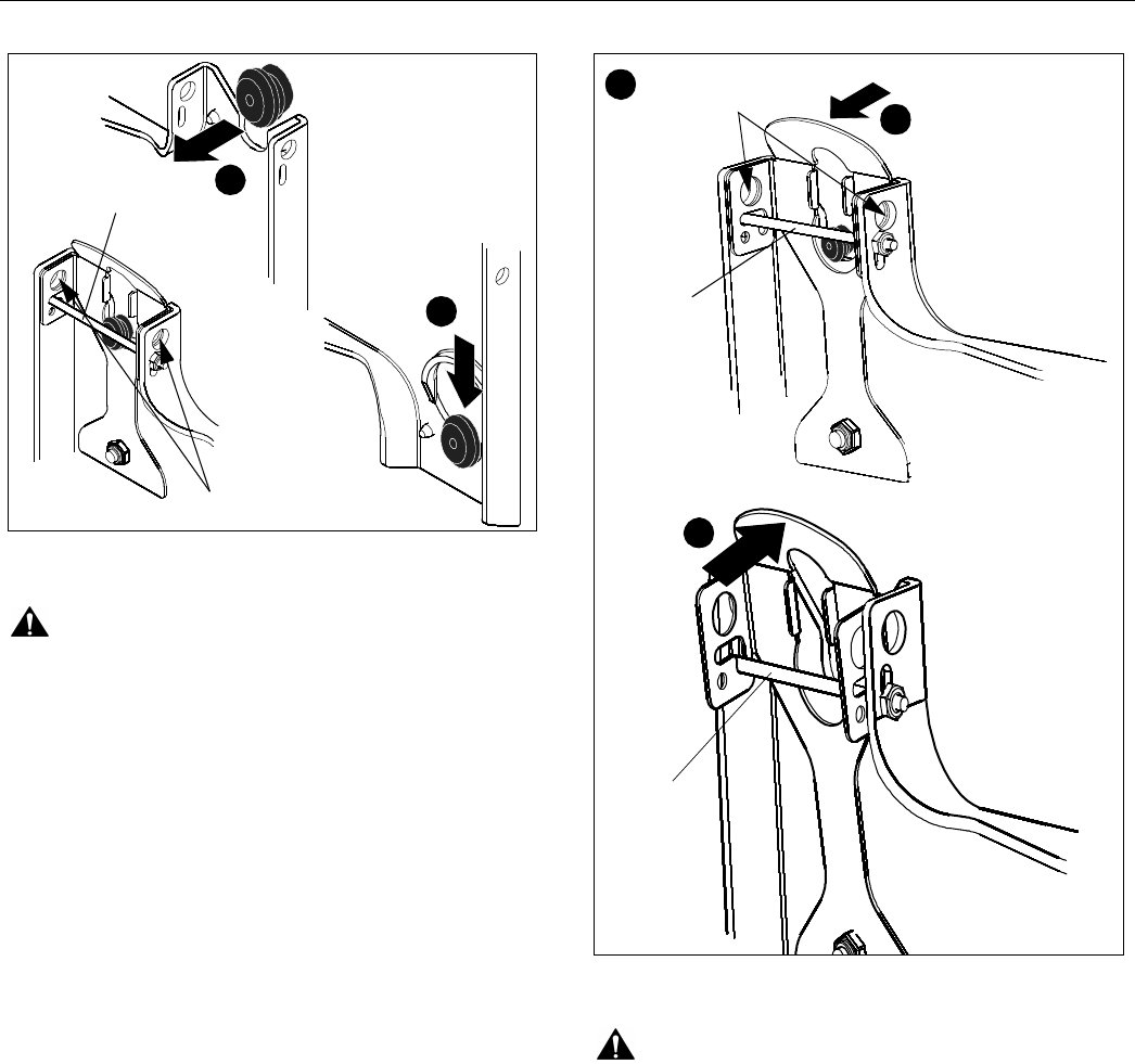
Figure 4
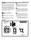
WARNING: IMPROPER INSTALLATION CAN LEAD TO
DISPLAY FALLING CAUSING SERIOUS PERSONAL
INJURY OR DAMAGE TO EQUIPMENT! Ensure mounting
buttons are completely engaged in mounting holes.
NOTE: Holes are provided in the faceplate for use with a
padlock or similar locking device, if desired. In addition,
the pin and nut may be removed from the upper holes
and moved to the lower holes for use as a more
permanent locking device. (See Figure 4)
3. Connect and secure power, audio and video cables.
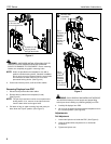
Removing Displays from PDC
1. Disconnect all power/audio/video cables.
2. Remove bolt or padlock from faceplate (if used).
(See Figure 5)
NOTE: The pin may have been used as a more permanent
locking device. If so, remove nut and pin and move
from the lower holes to the upper holes.
3. Pull back on flag on upper mounting hole and press pin
down down into "Open" position. (See Figure 5)
Figure 5
WARNING: EACH DISPLAY MAY WEIGH IN EXCESS OF
40 LBS EACH! Always use two people and proper lifting
techniques when installing or positioning displays on PDC.
4. Carefully lift displays from PDC.
5. Lift up on pin and place flag back against faceplate to return
it to "Closed" position. (See Figure 5)
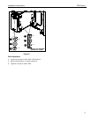
Adjustments
Roll Adjustment
1. Loosen two Nylock nuts inside the PDC. (See Figure 6)
2. Using the slotted holes, adjust the roll, or horizontal
movement.
3. Tighten two Nylock nuts.
1
2
May remove
pin and nut and
move to lower holes
A padlock or bolt
may be placed
through latch holes
move to
3
2
Remove bolt
or padlock
if used
Pin in
"Open"
position -
Pin in
"Closed"
position -
5
move to
"Open"
position to
"Closed"
position
remove
display
after display
is removed.