


Installation Instructions PDC Series
5
INSTALLATION
Preparing for Installation
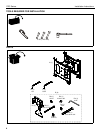
1. Attach click-lock flag kits (D) to PDC following instructions
included with the kits.
WARNING: FAILURE TO PROVIDE ADEQUATE
STRUCTURAL STRENGTH FOR THIS COMPONENT CAN
RESULT IN SERIOUS PERSONAL INJURY OR DAMAGE
TO EQUIPMENT! It is the installer’s responsibility to make
sure the structure to which this component is attached can
support five times the combined weight of all equipment.
Reinforce the structure as required before installing the
component.
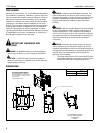
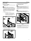
2. Determine if NPT pipe is 1-1/2" or 2".
• If NPT pipe is 1-1/2", proceed to Step 3.
• If NPT pipe is 2", loosen set screw and
remove the 1-1/2" to 2" pipe coupler, then
proceed to Step 3.(See Figure 1)
Figure 1
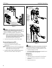
3. Thread the PDC (A) onto the NPT pipe extension and
tighten set screw. (See Figure 2)
Figure 2
4. Attach interface brackets to back of displays following
instructions included with the interface brackets.
Installing Displays on PDC
WARNING: EXCEEDING MAXIMUM WEIGHT CAPACITY
CAN LEAD TO SERIOUS PERSONAL INJURY OR
DAMAGE TO EQUIPMENT! It is the installers responsibility
to ensure the total amount of weight placed on the mount
does not exceed 400 lbs (181.44 kg) [200 lbs (90.72 kg) each
faceplate].
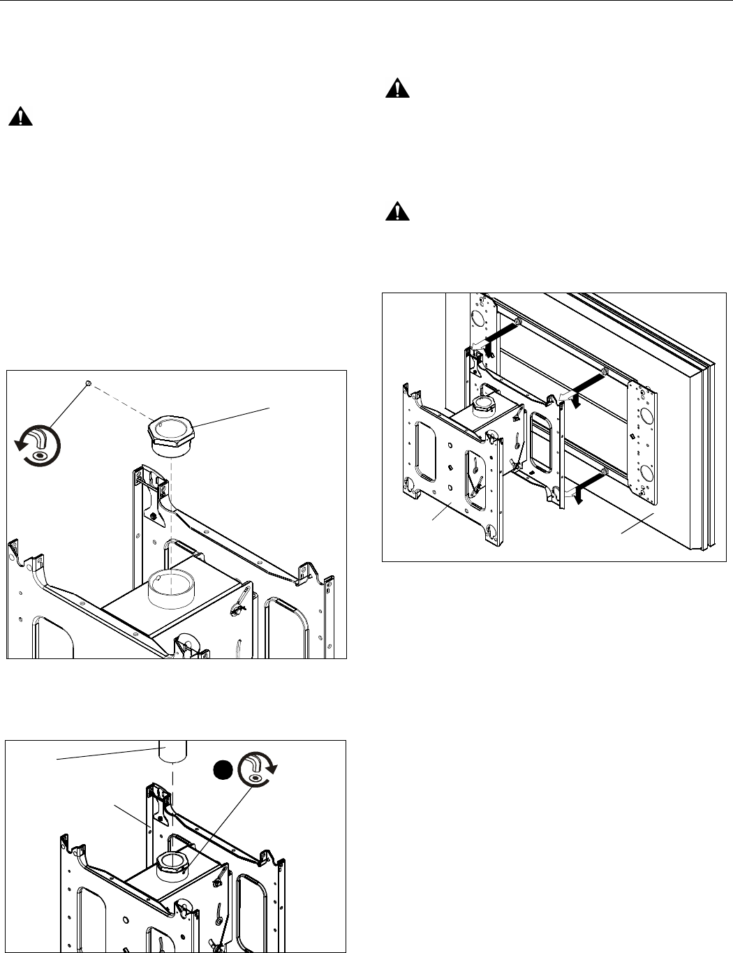
WARNING: DISPLAY MAY WEIGH IN EXCESS OF
40 LBS (18.14 KG)! Always use two people and proper lifting
techniques when installing or positioning display.
Figure 3
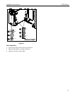
1. While supporting each side of display, align four mounting
buttons on display or interface bracket with four slots on
PDC. (See Figure 3)
2. Lower each display into place listening for audible "click" to
ensure recessed area of mounting buttons are properly
seated in lower area of mounting holes.(See Figure 4)
Set
Screw
Pipe
Coupler
(A)
1
Set
Screw
NPT
Pipe
(A)
Display