


MSS6000 Installation Instructions
6
Display Installation
The following procedure assumes that the proper
interface bracket for the display being mounted has
already been installed on the display.
If no interface bracket is present on display, install
bracket to display using the instructions included with the
interface bracket before proceeding.
If an interface bracket for the display being mounted
needs to be obtained, or additional assistance is
required, contact a Chief Customer Service
representative by calling 1-800-582-6480 or by visiting
www.chiefmfg.com.
NOTE: If the display being mounted has a height of more
than 24" the mount needs to be modified prior to
display installation.
(See Display More Than 24 Inches High on
page 5)
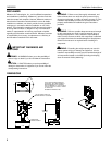
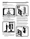
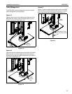
To install the display:
1. While supporting both sides of display, align four mounting
buttons on display or interface bracket with four mounting
holes in faceplate. (See Figures 5 and 6)
Figure 5
2. Lower display into place listening for audible "click" to
ensure recessed area of mounting buttons are properly
seated in lower area of mounting holes. (See Figures 5 & 6)
WARNING: IMPROPER INSTALLATION CAN LEAD TO
DISPLAY FALLING CAUSING SERIOUS PERSONAL
INJURY OR DAMAGE TO EQUIPMENT! Ensure mounting
buttons are completely engaged in mounting holes.
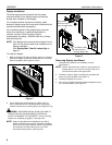
NOTE: Holes are provided in the faceplate for use with a
padlock or similar locking device, if desired. In addition,
the pin and nut may be removed from the upper holes
and moved to the lower holes for use as a more
permanent locking device. (See Figure 6).
Figure 6
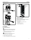
Removing Display from Mount
1. Remove bolt or padlock from faceplate (if used).
(See Figure 7)
NOTE: The pin may have been used as a more permanent
locking device. If so, remove nut and pin and move
from the lower holes to the upper holes.
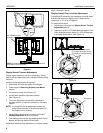
2. Pull back on flag on upper mounting hole and press pin
down into "Open" position. (See Figure 7)
3. Carefully lift display from mount.
4. Lift up on pin and place flag back against faceplate to return
it to "Closed" position. (See Figure 7)
1
1
2
May remove
pin and nut and
move to lower holes
A padlock or bolt
may be placed
through latch holes