


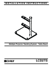


Installation Instructions LCD2TS
5
Assembly And Installation
For RPA Models Only
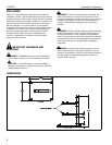
WARNING: Failure to provide adequate structural strength
for this component can result in serious personal injury or
damage to equipment. It is the installer’s responsibility to
make sure the structure to which this component is attached
can support five times the combined weight of all equipment.
Reinforce the structure as required before installing the
component.
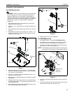
1. Set the base plate (B) on a flat stable work surface and
adjust the feet as necessary.
2. Thread the 1-1/2" pipe section (C) into the base plate and
tighten.
3. Secure NPT pipe to base plate using one 5/16-18 x 3/8" set
screw (I).
4. Attach RPA to projector arm (A) using four 1/4-20 X 1-1/2"
carriage bolts (H), four 1/4-20 acorn nuts (G) and 1/4" flat
washers (L). (See Figure 1)
Figure 1
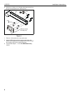
5. Slide both projector arms (A) onto the 1-1/2" vertical pipe
section (C) and secure using two 5/16-18 x 3/8" set screws
(I) on each arm. (See Figure 2)
6. Thread 1-1/2" safety nut (F) onto threaded end of the 1-1/2"
pipe section. (See Figure 2)
7. Mount projector hanging bracket to your projector (see RPA
instructions).
8. Partially thread 10-24 thumbscrews onto 10-24 studs at top
of hanger bracket plate. The quantity of thumbscrews may
vary from three to six.
9. Align studs with key slots of RPA, slide RPA into place, and
secure RPA by tightening thumbscrews.
Figure 2
10. Adjust projector for correct registration.
For RPM Models Only
1. Proceed with Steps 1-3 under For RPA Models Only.
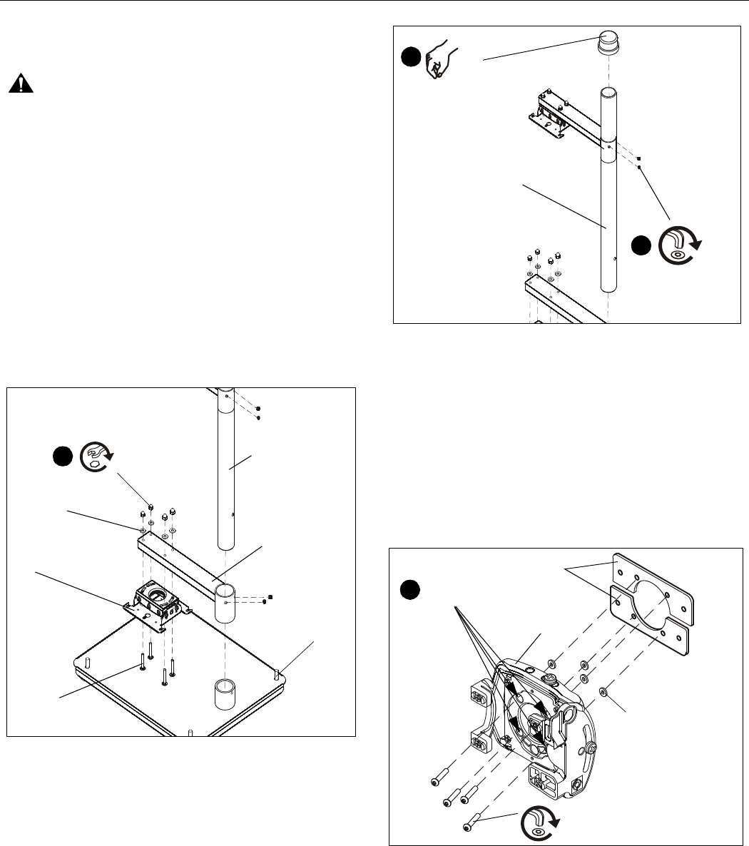
2. Place RPM on its top so that four screw holes are visible
through the square in the RPM base. (See Figure 3)
3. Insert four 1/4"-20x1-1/2" (K) button head cap screws into
the bottom of the RPM. (See Figure 3)
NOTE: The RPM base is not shown in Figure 3 for clarity only.
It should NOT be removed for this installation process.
Figure 3
4. Place four nylon spacers (M) onto the screws as shown in
Figure 3.
5. Tighten the screws through the nylon spacers and into the
two interface brackets (D). (See Figure 3)
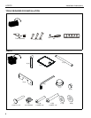
(H)x4
Adjustable
Feet
RPA
4
(G)x4
(L)x4
(C)
(A)
5
(I)x2
(C)
6
(F)
(K)x4
RPM base not
shown for
clarity only.
(D)
RPM
2
4 screw
holes
(M)x4