


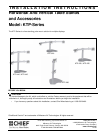


Installation Instructions Model: KTP-Series
5
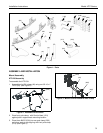
Figure 8: Secure Display to Centris Bracket
Attach Centris Head to Recessed Mount Display
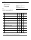
NOTE: Refer to Table 3 to select the applicable screw
and spacer combination.
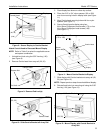
1. Uninstall end lock using the 5/32" hex key (120).
(see Figure 9)
2. Remove Centris head from array rail (20, 30).
Figure 9: Remove End Lock(s)
Figure 10: Slide Centris Bracket off Array Rail
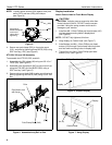
3. Place display face down on a clean dry surface.
4. Place four 3/8" or 3/4" nylon spacers (190 or 200)
over four mounting holes in display back (see Figure
11).
5. Align Centris head mounting holes with four nylon
spacers (see Figure 11).
6. Secure Centris head to display using four
M4 x 20mm Phillips pan head screws (170), or four
M4 x 30mm Phillips pan head screws (180)
(see Figure 11).
Figure 11: Mount Centris Bracket to Display
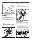
7. Slide display with Centris bracket onto array rail (20,
30) (see Figure 12).
NOTE: Repeat previous steps for each additional display.
8. Reinstall end locks into mounting rail using the 5/32"
hex key (120) (see Figure 13).
Figure 12: Mount Display with Centris Bracket to
Array Rail
Display
Centris Head
(20, 30)
(160)
Square Nut
End Lock
Centris Head
(20, 30)
Centris Head
(20, 30)
Display
Centris Head
Spacer
Phillips Pan Head Screw
(170 or 180)
(190 or 200)
Display with Centris Bracket
(20, 30)